Posts Tagged SDLC
Developing a Multi-Account AWS Environment Strategy
Posted by Gary A. Stafford in AWS, Cloud, DevOps, Enterprise Software Development, Technology Consulting on March 11, 2023
Explore twelve common patterns for developing an effective and efficient multi-account AWS environment strategy

Introduction
Every company is different: its organizational structure, the length of time it has existed, how fast it has grown, the industries it serves, its product and service diversity, public or private sector, and its geographic footprint. This uniqueness is reflected in how it organizes and manages its Cloud resources. Just as no two organizations are exactly alike, the structure of their AWS environments is rarely identical.
Some organizations successfully operate from a single AWS account, while others manage workloads spread across dozens or even hundreds of accounts. The volume and purpose of an organization’s AWS accounts are a result of multiple factors, including length of time spent on AWS, Cloud maturity, organizational structure and complexity, sectors, industries, and geographies served, product and service mix, compliance and regulatory requirements, and merger and acquisition activity.
“By design, all resources provisioned within an AWS account are logically isolated from resources provisioned in other AWS accounts, even within your own AWS Organizations.” (AWS)
Working with industry peers, the AWS community, and a wide variety of customers, one will observe common patterns for how organizations separate environments and workloads using AWS accounts. These patterns form an AWS multi-account strategy for operating securely and reliably in the Cloud at scale. The more planning an organization does in advance to develop a sound multi-account strategy, the less the burden that is required to manage changes as the organization grows over time.
The following post will explore twelve common patterns for effectively and efficiently organizing multiple AWS accounts. These patterns do not represent an either-or choice; they are designed to be purposefully combined to form a multi-account AWS environment strategy for your organization.
Patterns
- Pattern 1: Single “Uber” Account
- Pattern 2: Non-Prod/Prod Environments
- Pattern 3: Upper/Lower Environments
- Pattern 4: SDLC Environments
- Pattern 5: Major Workload Separation
- Pattern 6: Backup
- Pattern 7: Sandboxes
- Pattern 8: Centralized Management and Governance
- Pattern 9: Internal/External Environments
- Pattern 10: PCI DSS Workloads
- Pattern 11: Vendors and Contractors
- Pattern 12: Mergers and Acquisitions
Patterns 1–8 are progressively more mature multi-account strategies, while Patterns 9–12 represent special use cases for supplemental accounts.
Multi-Account Advantages
According to AWS’s whitepaper, Organizing Your AWS Environment Using Multiple Accounts, the benefits of using multiple AWS accounts include the following:
- Group workloads based on business purpose and ownership
- Apply distinct security controls by environment
- Constrain access to sensitive data (including compliance and regulation)
- Promote innovation and agility
- Limit the scope of impact from adverse events
- Support multiple IT operating models
- Manage costs (budgeting and cost attribution)
- Distribute AWS Service Quotas (fka limits) and API request rate limits
As we explore the patterns for organizing your AWS accounts, we will see how and to what degree each of these benefits is demonstrated by that particular pattern.
AWS Control Tower
Discussions about AWS multi-account environment strategies would not be complete without mentioning AWS Control Tower. According to the documentation, “AWS Control Tower offers a straightforward way to set up and govern an AWS multi-account environment, following prescriptive best practices.” AWS Control Tower includes Landing zone, described as “a well-architected, multi-account environment based on security and compliance best practices.”
AWS Control Tower is prescriptive in the Shared accounts it automatically creates within its AWS Organizations’ organizational units (OUs). Shared accounts created by AWS Control Tower include the Management, Log Archive, and Audit accounts. The previous standalone AWS service, AWS Landing Zone, maintained slightly different required accounts, including Shared Services, Log Archive, Security, and optional Network accounts. Although prescriptive, AWS Control Tower is also flexible and relatively unopinionated regarding the structure of Member accounts. Member accounts can be enrolled or unenrolled in AWS Control Tower.
You can decide whether or not to implement AWS Organizations or AWS Control Tower to set up and govern your AWS multi-account environment. Regardless, you will still need to determine how to reflect your organization’s unique structure and requirements in the purpose and quantity of the accounts you create within your AWS environment.
Common Multi-Account Patterns
While working with peers, community members, and a wide variety of customers, I regularly encounter the following twelve patterns for organizing AWS accounts. As noted earlier, these patterns do not represent an either-or choice; they are designed to be purposefully combined to form a multi-account AWS environment strategy for your organization.
Pattern 1: Single “Uber” Account
Organizations that effectively implement Pattern 1: Single “Uber” Account organize and separate environments and workloads at the sub-account level. They often use Amazon Virtual Private Cloud (Amazon VPC), an AWS account-level construct, to organize and separate environments and workloads. They may also use Subnets (VPC-level construct) or AWS Regions and Availability Zones to further organize and separate environments and workloads.
Pros
- Few, if any, significant advantages, especially for customer-facing workloads
Cons
- Decreased ability to limit the scope of impact from adverse events (widest blast radius)
- If the account is compromised, then all the organization’s workloads and data, possibly the entire organization, are potentially compromised (e.g., Ransomware attacks such as Encryptors, Lockers, and Doxware)
- Increased risk that networking or security misconfiguration could lead to unintended access to sensitive workloads and data
- Increased risk that networking, security, or resource management misconfiguration could lead to broad or unintended impairment of all workloads
- Decreased ability to perform team-, environment-, and workload-level budgeting and cost attribution
- Increased risk of resource depletion (soft and hard service quotas)
- Reduced ability to conduct audits and demonstrate compliance
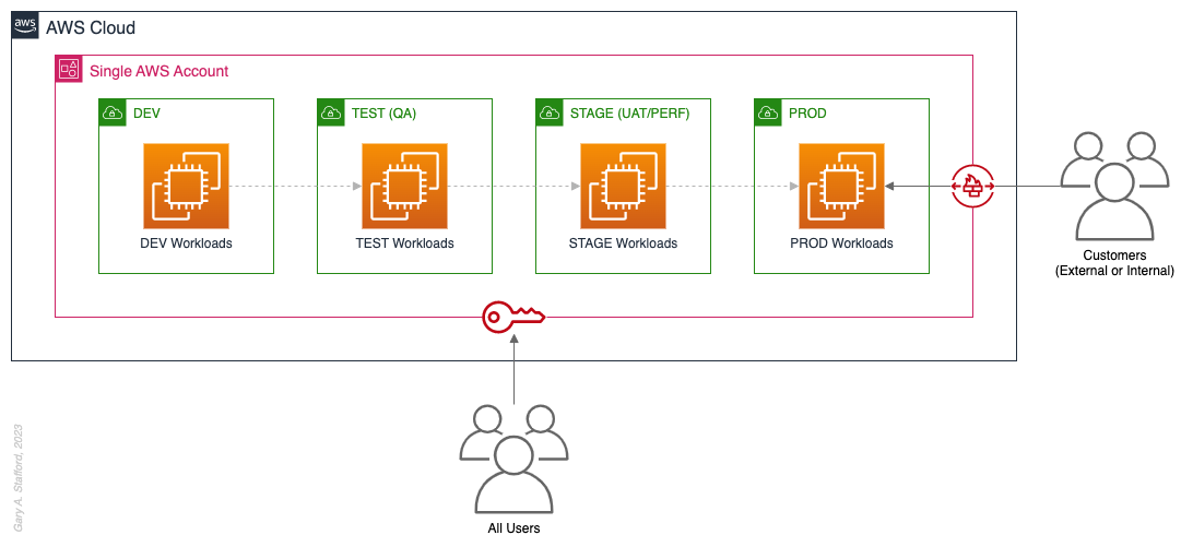
Pattern 2: Non-Prod/Prod Environments
Organizations that effectively implement Pattern 2: Non-Prod/Prod Environments organize and separate non-Production workloads from Production (PROD) workloads using separate AWS accounts. Most often, they use Amazon VPCs within the non-Production account to separate workloads or Software Development Lifecycle (SDLC) environments, most often Development (DEV), Testing (TEST) or Quality Assurance (QA), and Staging (STAGE). Alternatively, these environments might also be designated as “N-1” (previous release), “N” (current release), “N+1” (next release), “N+2” (in development), and so forth, based on the currency of that version of that workload.
In some organizations, the Staging environment is used for User Acceptance Testing (UAT), performance (PERF) testing, and load testing before releasing workloads to Production. While in other organizations, STAGE, UAT, and PERF are each treated as separate environments at the account or VPC level.
Isolating Production workloads into their own account(s) and strictly limiting access to those workloads represents a significant first step in improving the overall maturity of your multi-account AWS environment strategy.
Pros
- Limits the scope of impact on Production as a result of adverse non-Production events (narrower blast radius)
- Logical separation and security of Production workloads and data
- Tightly control and limit access to Production, including the use of Break-the-Glass procedures (aka Break-glass or BTG); draws its name from “breaking the glass to pull a fire alarm”
- Eliminate the risk that non-Production networking or security misconfiguration could lead to unintended access to sensitive Production workloads and data
- Eliminate the chance that non-Production networking, security, or resource management misconfiguration could lead to broad or unintended impairment of Production workloads
- Conduct audits and demonstrate compliance with Production workloads
Cons
- If the Production account is compromised, then all the organization’s customer-facing workloads and data are potentially compromised
- Decreased ability to perform team-, environment-, and workload-level budgeting and cost attribution in the shared non-Production environment
- Increased risk of resource depletion (soft and hard service quotas) in the non-Production environment account
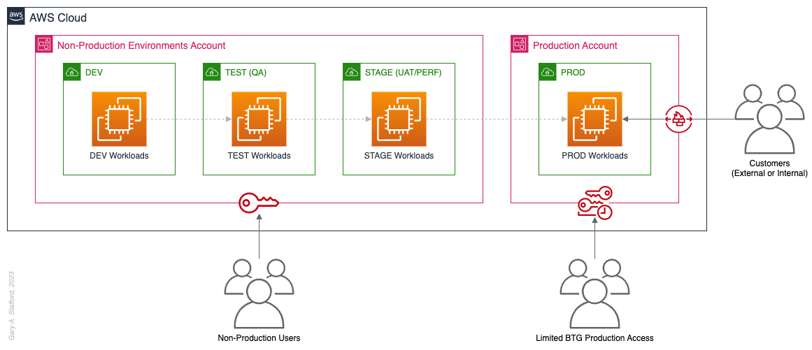
Pattern 3: Upper/Lower Environments
The next pattern, Pattern 3: Upper/Lower Environments, is a finer-grain variation of Pattern 2. With Pattern 3, we split all “Lower” environments into a single account and each “Upper” environment into its own account. In the software development process, initial environments, such as CI/CD for automated testing of code and infrastructure, Development, Test, UAT, and Performance, are called “Lower” environments. Conversely, later environments, such as Staging, Production, and even Disaster Recovery (DR), are called “Upper” environments. Upper environments typically require isolation for stability during testing or security for Production workloads and sensitive data.
Often, courser-grain patterns like Patterns 1–3 are carryovers from more traditional on-premises data centers, where compute, storage, network, and security resources were more constrained. Although these patterns can be successfully reproduced in the Cloud, they may not be optimal compared to more “cloud native” patterns, which provide improved separation of concerns.

Pros
- Limits the scope of impact on individual Upper environments as a result of adverse Lower environment events (narrower blast radius)
- Increased stability of Staging environment for critical UAT, performance, and load testing
- Logical separation and security of Production workloads and data
- Tightly control and limit access to Production, including the use of BTG
- Eliminate the risk that non-Production networking or security misconfiguration could lead to unintended access to sensitive Production workloads and data
- Eliminate the chance that non-Production networking, security, or resource management misconfiguration could lead to broad or unintended impairment of Production workloads
- Conduct audits and demonstrate compliance with Production workloads
Cons
- If the Production account is compromised, then all the organization’s customer-facing workloads and data are potentially compromised (e.g., Ransomware attack)
- Decreased ability to perform team-, environment-, and workload-level budgeting and cost attribution in the shared Lower environment
- Increased risk of resource depletion (soft and hard service quotas) in the Lower environment account
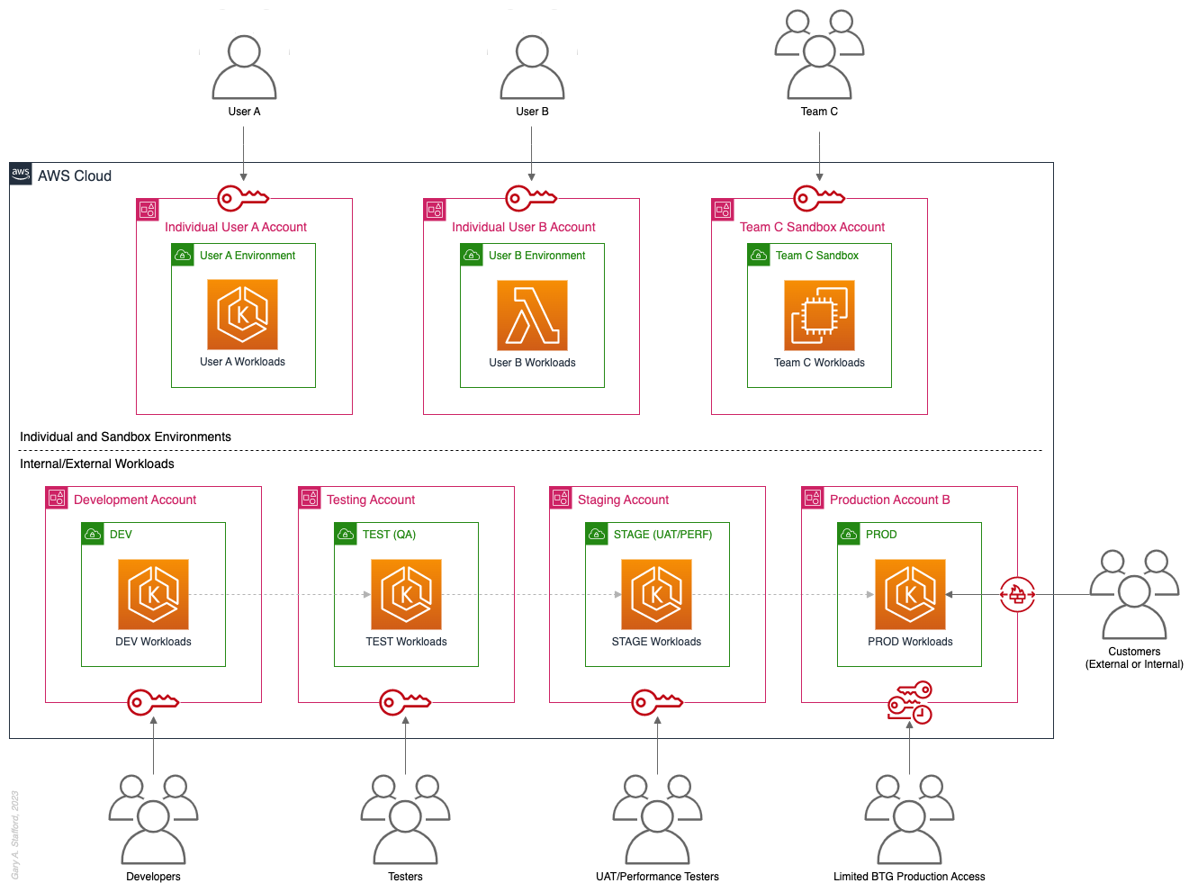
Pattern 4: SDLC Environments
The next pattern, Pattern 4: SDLC Environments, is a finer-grain variation of Pattern 3. With Pattern 4, we gain complete separation of each SDLC environment into its own AWS account. Using AWS services like AWS IAM Identity Center (fka AWS SSO), the Security team can enforce least-privilege permissions at an AWS Account level to individual groups of users, such as Developers, Testers, UAT, and Performance testers.
Based on my experience, Pattern 4 represents the minimal level of workload separation an organization should consider when developing its multi-account AWS environment strategy. Although Pattern 4 has a number of disadvantages, when combined with subsequent patterns and AWS best practices, this pattern begins to provide a scalable foundation for an organization’s growing workload portfolio.

Patterns, such as Pattern 4, not only apply to traditional software applications and services. These patterns can be applied to data analytics, AI/ML, IoT, media services, and similar workloads where separation of environments is required.

Pros
- Limits the scope of impact on one SDLC environment as a result of adverse events in another environment (narrower blast radius)
- Logical separation and security of Production workloads and data
- Increased stability of each SDLC environment
- Tightly control and limit access to Production, including the use of BTG
- Reduced risk that non-Production networking or security misconfiguration could lead to unintended access to sensitive Production workloads and data
- Reduced risk that non-Production networking, security, or resource management misconfiguration could lead to broad or unintended impairment of Production workloads
- Conduct audits and demonstrate compliance with Production workloads
- Increased ability to perform budgeting and cost attribution for each SDLC environment
- Reduced risk of resource depletion (soft and hard service limits) and IP conflicts and exhaustion within any single SDLC environment
Cons
- All workloads for each SDLC environment run within a single account, including Production, increasing the potential scope of impact from adverse events within that environment’s account
- If the Production account is compromised, then all the organization’s customer-facing workloads and data are potentially compromised
- Decreased ability to perform workload-level budgeting and cost attribution
Pattern 5: Major Workload Separation
The next pattern, Pattern 5: Major Workload Separation, is a finer-grain variation of Pattern 4. With Pattern 5, we separate each significant workload into its own separate SDLC environment account. The security team can enforce fine-grain least-privilege permissions at an AWS Account level to individual groups of users, such as Developers, Testers, UAT, and Performance testers, by their designated workload(s).
Pattern 5 has several advantages over the previous patterns. In addition to the increased workload-level security and reliability benefits, Pattern 5 can be particularly useful for organizations that operate significantly different technology stacks and specialized workloads, particularly at scale. Different technology stacks and specialized workloads often each have their own unique development, testing, deployment, and support processes. Isolating these types of workloads will help facilitate the support of multiple IT operating models.

Pros
- Limits the scope of impact on an individual workload as a result of adverse events from another workload or SDLC environment (narrowest blast radius)
- Increased ability to perform team-, environment-, and workload-level budgeting and cost attribution
Cons
- If the Production account is compromised, then all the organization’s customer-facing workloads and data are potentially compromised (e.g., Ransomware attack)
Pattern 6: Backup
In the earlier patterns, we mentioned that if the Production account were compromised, all the organization’s customer-facing workloads and data could be compromised. According to TechTarget, 2022 was a breakout year for Ransomware attacks. According to the US government’s CISA.gov website, “Ransomware is a form of malware designed to encrypt files on a device, rendering any files and the systems that rely on them unusable. Malicious actors then demand ransom in exchange for decryption.”
According to AWS best practices, one of the recommended preparatory actions to protect and recover from Ransomware attacks is backing up data to an alternate account using tools such as AWS Backup and an AWS Backup vault. Solutions such as AWS Backup protect and restore data regardless of how it was made inaccessible.
In Pattern 6: Backup, we create one or more Backup accounts to protect against unintended data loss or account compromise. In the example below, we have two Backup accounts, one for Production data and one for all non-Production data.

Pros
- If the Production account is compromised (e.g., Ransomware attacks such as Encryptors, Lockers, and Doxware), there are secure backups of data stored in a separate account, which can be used to restore or recreate the Production environment
Cons
- Few, if any, significant disadvantages when combined with previous patterns and AWS best-practices
Pattern 7: Sandboxes
The following pattern, Pattern 7: Sandboxes, supplements the previous patterns, designed to address the needs of an organization to allow individual users and teams to learn, build, experiment, and innovate on AWS without impacting the larger organization’s AWS environment. To quote the AWS blog, Best practices for creating and managing sandbox accounts in AWS, “Many organizations need another type of environment, one where users can build and innovate with AWS services that might not be permitted in production or development/test environments because controls have not yet been implemented.” Further, according to TechTarget, “a Sandbox is an isolated testing environment that enables users to run programs or open files without affecting the application, system, or platform on which they run.”
Due to the potential volume of individual user and team accounts, sometimes referred to as Sandbox accounts, mature infrastructure automation practices, cost controls, and self-service provisioning and de-provisioning of Sandbox accounts are critical capabilities for the organization.
Pros
- Allow individual users and teams to learn, build, experiment, and innovate on AWS without impacting the rest of the organization’s AWS environment
Cons
- Without mature automation practices, cost controls, and self-service capabilities, managing multiple individual and team Sandbox accounts can become unwieldy and costly
Pattern 8: Centralized Management and Governance
We discussed AWS Control Tower at the beginning of this post. AWS Control Tower is prescriptive in creating Shared accounts within its AWS Organizations’ organizational units (OUs), including the Management, Log Archive, and Audit accounts. AWS encourages using AWS Control Tower to orchestrate multiple AWS accounts and services on your behalf while maintaining your organization’s security and compliance needs.
As exemplified in Pattern 8: Centralized Management and Governance, many organizations will implement centralized management whether or not they decide to implement AWS Control Tower. In addition to the Management account (payer account, fka master account), organizations often create centralized logging accounts, and centralized tooling (aka Shared services) accounts for functions such as CI/CD, IaC provisioning, and deployment. Another common centralized management account is a Security account. Organizations use this account to centralize the monitoring, analysis, notification, and automated mitigation of potential security issues within their AWS environment. The Security accounts will include services such as Amazon Detective, Amazon Inspector, Amazon GuardDuty, and AWS Security Hub.

Pros
- Increased ability to manage and maintain multiple AWS accounts with fewer resources
- Reduced duplication of management resources across accounts
- Increased ability to use automation and improve the consistency of processes and procedures across multiple accounts
Cons
- Few, if any, significant disadvantages when combined with previous patterns and AWS best-practices
Pattern 9: Internal/External Environments
The next pattern, Pattern 9: Internal/External Environments, focuses on organizations with internal operational systems (aka Enterprise systems) in the Cloud and customer-facing workloads. Pattern 9 separates internal operational systems, platforms, and workloads from external customer-facing workloads. For example, an organization’s divisions and departments, such as Sales and Marketing, Finance, Human Resources, and Manufacturing, are assigned their own AWS account(s). Pattern 9 allows the Security team to ensure that internal departmental or divisional users are isolated from users who are responsible for developing, testing, deploying, and managing customer-facing workloads.
Note that the diagram for Pattern 9 shows remote users who access AWS End User Computing (EUC) services or Virtual Desktop Infrastructure (VDI), such as Amazon WorkSpaces and Amazon AppStream 2.0. In this example, remote workers have secure access to EUC services provisioned in a separate AWS account, and indirectly, internal systems, platforms, and workloads.

Pros
- Separation of internal operational systems, platforms, and workloads from external customer-facing workloads
Cons
- Few, if any, significant disadvantages when combined with previous patterns and AWS best-practices
Pattern 10: PCI DSS Workloads
The next pattern, Pattern 10: PCI DSS Workloads, is a variation of previous patterns, which assumes the existence of Payment Card Industry Data Security Standard (PCI DSS) workloads and data. According to the AWS, “PCI DSS applies to entities that store, process, or transmit cardholder data (CHD) or sensitive authentication data (SAD), including merchants, processors, acquirers, issuers, and service providers. The PCI DSS is mandated by the card brands and administered by the Payment Card Industry Security Standards Council.”
According to AWS’s whitepaper, Architecting for PCI DSS Scoping and Segmentation on AWS, “By design, all resources provisioned within an AWS account are logically isolated from resources provisioned in other AWS accounts, even within your own AWS Organizations. Using an isolated account for PCI workloads is a core best practice when designing your PCI application to run on AWS.” With Pattern 10, we separate non-PCI DSS and PCI DSS Production workloads and data. The assumption is that only Production contains PCI DSS data. Data in lower environments is synthetically generated or sufficiently encrypted, masked, obfuscated, or tokenized.
Note that the diagram for Pattern 10 shows Administrators. Administrators with different spans of responsibility and access are present in every pattern, whether specifically shown or not.

Pros
- Increased ability to meet compliance requirements by separating non-PCI DSS and PCI DSS Production workloads
Cons
- Few, if any, significant disadvantages when combined with previous patterns and AWS best-practices
Pattern 11: Vendors and Contractors
The next pattern, Pattern 11: Vendors and Contractors, is focused on organizations that employ contractors or use third-party vendors who provide products and services that interact with their AWS-based environment. Like Pattern 10, Pattern 11 allows the Security team to ensure that contractor and vendor-based systems’ access to internal systems and customer-facing workloads is tightly controlled and auditable.
Vendor-based products and services are often deployed within an organization’s AWS environment without external means of ingress or egress. Alternatively, a vendor’s product or service may have a secure means of ingress from or egress to external endpoints. Such is the case with some SaaS products, which ship an organization’s data to an external aggregator for analytics or a security vendor’s product that pre-filters incoming data, external to the organization’s AWS environment. Using separate AWS accounts can improve an organization’s security posture and mitigate the risk of adverse events on the organization’s overall AWS environment.

Pros
- Ensure access to internal systems and customer-facing workloads by contractors and vendor-based systems is tightly controlled and auditable
Cons
- Few, if any, significant disadvantages when combined with previous patterns and AWS best-practices
Pattern 12: Mergers and Acquisitions
The next pattern, Pattern 12: Mergers and Acquisitions, is focused on managing the integration of external AWS accounts as a result of a merger or acquisition. This is a common occurrence, but the exact details of how best to handle the integration of two or more integrations depend on several factors. Factors include the required level of integration, for example, maintaining separate AWS Organizations, maintaining different AWS accounts, or merging resources from multiple accounts. Other factors that might impact account structure include changes in ownership or payer of acquired accounts, existing acquired cost-savings agreements (e.g., EDPs, PPAs, RIs, and Savings Plans), and AWS Marketplace vendor agreements. Even existing authentication and authorization methods of the acquiree versus the acquirer (e.g., AWS IAM Identity Center, Microsoft Active Directory (AD), Azure AD, and external identity providers (IdP) like Okta or Auth0).
The diagram for Pattern 12 attempts to show a few different M&A account scenarios, including maintaining separate AWS accounts for the acquirer and acquiree (e.g., acquiree’s Manufacturing Division account). If desired, the accounts can be kept independent but managed within the acquirer’s AWS Organizations’ organization. The diagram also exhibits merging resources from the acquiree’s accounts into the acquirer’s accounts (e.g., Sales and Marketing accounts). Resources will be migrated or decommissioned, and the account will be closed.

Pros
- Maintain separation between an acquirer and an acquiree’s AWS accounts within a single organization’s AWS environment
- Potentially consolidate and maximize cost-saving advantages of volume-related financial agreements and vendor licensing
Cons
- Migrating workloads between different organizations, depending on their complexity, requires careful planning and testing
- Consolidating multiple authentication and authorization methods requires careful planning and testing to avoid improper privileges
- Consolidating and optimizing separate licensing and cost-saving agreements between multiple organizations requires careful planning and an in-depth understanding of those agreements
Multi-Account AWS Environment Example
You can form an efficient and effective multi-account strategy for your organization by purposefully combining multiple patterns. Below is an example of combining the features of several patterns: Major Workload Separation, Backup, Sandboxes, Centralized Management and Governance, Internal/External Environments, and Vendors and Contractors.
According to AWS, “You can use AWS Organizations’ organizational units (OUs) to group accounts together to administer as a single unit. This greatly simplifies the management of your accounts.” If you decide to use AWS Organizations, each set of accounts associated with a pattern could correspond to an OU: Major Workload A, Major Workload B, Sandboxes, Backups, Centralized Management, Internal Environments, Vendors, and Contractors.

Conclusion
This post taught us twelve common patterns for effectively and efficiently organizing your AWS accounts. Instead of an either-or choice, these patterns are designed to be purposefully combined to form a multi-account strategy for your organization. Having a sound multi-account strategy will improve your security posture, maintain compliance, decrease the impact of adverse events on your AWS environment, and improve your organization’s ability to safely and confidently innovate and experiment on AWS.
Recommended References
- Establishing Your Cloud Foundation on AWS (AWS Whitepaper)
- Organizing Your AWS Environment Using Multiple Accounts (AWS Whitepaper)
- Building a Cloud Operating Model (AWS Whitepaper)
- AWS Security Reference Architecture (AWS Prescriptive Guidance)
- AWS Security Maturity Model (AWS Whitepaper)
- AWS re:Invent 2022 — Best practices for organizing and operating on AWS (YouTube Video)
- AWS Break Glass Role (GitHub)
🔔 To keep up with future content, follow Gary Stafford on LinkedIn.
This blog represents my viewpoints and not those of my employer, Amazon Web Services (AWS). All product names, logos, and brands are the property of their respective owners.
Operational Readiness Analysis
Posted by Gary A. Stafford in Continuous Delivery, DevOps, Software Development on October 12, 2016
“Analysis: a detailed examination of the elements or structure of something, typically as a basis for discussion or interpretation.” — Google
Introduction
Recently, I had the opportunity, along with a colleague, to perform an operational readiness analysis of a client’s new application platform. The platform was in late-stage development, only a few weeks from going live. Being relatively new to the project team, our objective was to determine the amount of work remaining to make the platform operational, from a technical perspective. As well, we wanted to ensure there were no gaps in the project’s scope, as it related to technical operational readiness.
There were various approaches we could have taken to establish the amount of unfinished work and any existing gaps. We could have reviewed the state of the project in the client’s Agile project management system. We could have discussed the project’s state with the Product Owner, Project Manager, Team Lead, and Business Analyst. Neither of these methods on their own would have provided us with a complete picture.
The approach we ultimately took was what we’ve coined, an Operational Readiness Analysis, or our trendier title, the ‘State of the DevOps’. This approach is particularly effective and highly interactive. The analysis may be conducted at any stage of the Software Development Lifecycle (SDLC), to review a project’s operational state of readiness. The analysis involves five simple steps:
- Categorize
- Itemize
- Organize
- Prioritize
- Document
Grab Your Post-It Notes
We began, where all good ThoughtWorkers tend to begin, with a meeting room, whiteboard, dry-erase markers, and lots of brightly colored Post-It notes. ThoughtWorkers do love their Post-It notes. We gathered a small subset of the project team, including the Product Owner, Project Manager, and the team’s DevOps Engineer.
Step 1: Categorize
To start, we broadly categorized the operational requirements into buckets of work. In my experience, categorization typically takes one of two forms, either the use of role-based descriptors, like ‘Security’ and ‘Monitoring’, or the use of the ‘ilities’, such as ‘Scalability’ and ‘Maintainability’.
The ‘ilities’ are often referenced in regards to software architecture and the functional and nonfunctional requirements (NFRs) of a project. Although there are many ‘ilities’, project requirements frequently include Usability, Scalability, Maintainability, Reliability, Testability, Availability, and Serviceability. Although I enjoy referring to the ‘ilities’ when drafting project requirements, I find a broad audience more readily understands the high-level category descriptions.
We collectively agreed on eight categories, in addition to a catch-all ‘Other’ category, and distributed them on the whiteboard.

Role-based categories tend to include the following:
- Security and Compliance
- Monitoring and Alerting
- Logging
- Continuous Integration and Delivery
- Release Management
- Configuration
- Environment Management
- Infrastructure
- Networking
- Data Management
- High Availability and Fault Tolerance
- Performance
- Backup and Restoration
- Support and Maintenance
- Documentation and Training
- Technical Debt
- Other
Step 2: Itemize
Next, each person placed as many Post-It notes as they wanted, below the categories on the whiteboard. Each Post-It represented an item someone felt needed to be addressed as part the analysis. Items might represent requirements currently in progress, or requirements still untouched in the project’s backlog. A Post-It note might contain a new requirement. Maybe there is a question about an aspect of the project’s relative importance, or there were concerns about how an aspect of the project had been implemented.
Participants placed an average of five to ten Post-It notes on the whiteboard. The end product was a collective mind-map of the project’s operational state (the following is only an example and doesn’t represent the actual results of any real client analysis).

Whereas categories tend to be generic in nature, the items are usually particular to the project, and it’s technology choices. The ‘Monitoring/Logging’ category might include individual items such as ‘Log Rotation Policy’ or ‘Splunk vs. ELK?’. The ‘Security’ category might include individual items such as ‘Need Password Rotation’ or ‘SSL Certificate Management’.
Participants often use one or two words to summarize more complex thoughts. For example, ‘Rollback’ might be stating, ‘we still don’t have a good rollback strategy for the database’. ‘Release Frequency’ may be questioning, ‘why can’t we release more frequently?’. Make sure to discuss and capture the participant’s full thoughts behind each Post-It, the during the Organize, Prioritize, and Document stages.
Don’t let participants give up too soon placing Post-It notes on the board. Often, one participant’s Post-It will spark additional thoughts other team members. Don’t be afraid to suggest a few items, if the group needs some initial motivation. Lastly, fear not, it’s never too late to go back and add missing items, uncovered in later stages of analysis.
Step 3: Organize
Quickly and non-judgmentally, review all items on the whiteboard. Group duplicates together. Ask for clarification on items where necessary. Move miscategorized items, if the author and team agree there is a more appropriate category.
Examine the ‘Other’ category. If there are items in the ‘Other’ category that are similar, consider adding a new category to capture them. Maybe the team missed identifying a key category, earlier. Conversely, there is nothing wrong with leaving a few stragglers in the ‘Other’ category; don’t overthink the exercise.
Participants should leave this stage with a general understanding of each item on the whiteboard.
Step 4: Prioritize
With all items identified, organized, and understood, discuss each item’s status. Does the item represent incomplete requirements? Does everyone agree an item’s requirements are complete? Team members may not agree on the completeness of particular items. Inconsistencies may reflect unclear requirements. More often, I find, disagreements are a result of an inconsistent or incomplete implementation of requirements across environments — Development, QA, Performance, Staging, and Production.
Why are operational requirements frequently implemented inconsistently? Often, a story is played early in the development stage, prior to all environments being available. For example, a story is played to add monitoring to Development and QA. The story is completed, tested, and closed. Afterward, the Performance environment is created. Later yet, the Staging and Production environments are created. But, there are no new stories to address monitoring the new environments.
One way to avoid this common issue with operational requirements is an effective DevOps automation strategy. In this example, an effective strategy would mean all new environments would get monitoring, automatically. The story should broadly address monitoring, and not, short-sightedly, monitoring of specific environments.
Often, only one or two project team members are responsible for ‘all the DevOps stuff’. They alone possess an accurate perspective on an item’s current status.
Gain agreement from the Product Owner, Project Manager, and key team members on the priority of incomplete requirements. Are they ‘Day One’ must-haves, or ‘Day Two’ and can be completed after the application goes live? Flag all high-priority items.
If the status of an item is unknown, such as ‘why is the QA environment always down?!’, note it as an open question and move on. If the item simply requires a quick answer to resolve, like ‘do we backup the database?’, answer it (‘the database is replicated and backed up daily’) and move on.

Step 5: Document
Snap a picture of the whiteboard and document its contents. We chose the client’s knowledge management system as a vehicle to share the whiteboard’s results. We created a table with columns for Category, Item, Description, Priority, Owner, and Notes. Also, it’s helpful to have a column for the project’s corresponding Story ID or Defect ID. Along with the whiteboard, capture key discussion points, questions, and concerns, raised by the participants.
Step 5: Document
Snap a picture of the whiteboard and document its contents. We chose Confluence to share the whiteboard results, using a table with columns for Category, Item, Description, Priority, Owner, and Notes. We also bulleted all key discussion points, questions, and concerns, raised by the participants.

Make the analysis results available to all team members. Let the team ask questions and poke holes in the results. Adjust the results if necessary.
Next Steps
The actions you take, given the results of the analysis, are up to you. In our case, we ensured all high-priority items were called out on the team’s Agile board. Any new items were captured in the client’s Agile project management system. Finally, we ensured open questions and concerns were addressed in a timely fashion. We continue to track each item’s status weekly, throughout the launch and post-launch periods.
We anticipate conducting a follow-up analysis, thirty days after launch. The goal will be to evaluate the effectiveness of the first analysis and identify additional operational needs as the application enters a business-as-usual (BAU) application lifecycle phase.
Postscript: the ‘ilities’
The ‘ilities’, courtesy of codesqueeze.com and en.wikipedia.org
- Scalability
The capability of a system, network, or process to handle a growing amount of work or its potential to be enlarged to accommodate that growth. - Testability
The practical feasibility of observing a reproducible series of such counterexamples if they do exist. - Reliability (Resilience)
The ability of a system or component to perform its required functions under stated conditions for a specified time. - Usability (Performance)
The degree to which software can be used by specified consumers to achieve quantified objectives with effectiveness, efficiency, and satisfaction in a quantified context of use. - Serviceability (Supportability)
The ability of technical support personnel to install, configure, and monitor computer products, identify exceptions or faults, debug or isolate faults to root cause analysis, and provide hardware or software maintenance in pursuit of solving a problem and restoring the product into service. - Availability
The proportion of time a system is in a functioning condition. Defined in the service-level agreement (SLA). - Maintainability
The ease with which a product can be maintained. Isolate and correct defects or their cause, prevent unexpected breakdowns, maximize a product’s useful life, maximize efficiency, reliability, and safety, meet new requirements, make future maintenance easier, and cope with a changed environment.
All opinions in this post are my own and not necessarily the views of my current employer or their clients.
Building a Deployment Pipeline Using Git, Maven, Jenkins, and GlassFish (Part 2 of 2)
Posted by Gary A. Stafford in Build Automation, DevOps, Enterprise Software Development, Software Development on November 13, 2013
Build an automated deployment pipeline for your Java EE applications using leading open-source technologies, including NetBeans, Git, Maven, JUnit, Jenkins, and GlassFish. All source code for this post is available on GitHub.

Introduction
In part 1, Building a Deployment Pipeline Using Git, Maven, Jenkins, and GlassFish (Part 1 of 2), we built the first part of our basic deployment pipeline using leading open-source technologies. In part 2, we will use Jenkins CI Server and Oracle GlassFish Application Server to complete our deployment pipeline.
To review, the three main goals of our deployment pipeline are continuous integration, automated testing, and continuous deployment. Our objective is to automatically compile, test, assemble, and deploy our Java EE application to multiple environments, as the project progresses through the software development life cycle (SDLC).
Setting up Git Server
As I mentioned in part 1, as a part of a development team using Git, you would place your project on a remote Git Server. You and your team members would each clone the repository from the Git Server to your local development environments. You and your team would commit your code changes locally, then pull, merge, and push your changes back to the remote Git Server. Jenkins will pull the project’s source code from the Git Server.
In part 1 of this post, we just created a local Git repository. In part 2, we will properly set-up our project on a remote Git Server. First, we need to export our local repository into a new, bare repository on the Git Server. The Git term, ‘bare repository’, refers to a repository that does not contain a working directory. The repository has no working copies of your source files. You only use the bare repository to clone, pull from, and push to. The bare repository contains a .git extension (i.e. ssh://user@server:/git-repos/myproject.git).
From the root of your remote Git Server repository, execute the following command, substituting the path to your local project. If your Git Server is on a separate machine that your local project repository, you will need to copy the new bare repository to the remote Git Server. This involves a few simple steps, explained in this post, and at git-scm.com.
| git clone --bare {path-to-existing-local-repository}\{name-of-repository} {name-of-repository}.git |

Export Local Project to New Bare Repository
Once you have created the repository on the remote Git Server, I would recommend you clone the remote repository to your local machine and discard your original local repository from part 1 of the post. You don’t have to do this step, but cloning fresh from the server will make sure Git is working correctly. The screen grabs below illustrate an example of cloning a new repository to my local NetBeans Project folder.

Clone New Bare Server Repository – Screen 1

Clone New Bare Server Repository – Screen 2

Clone New Bare Server Repository – Screen 3
Configuring Jenkins
The diagram below illustrates the deployment pipeline from Git Server to Jenkins to GlassFish in finer detail. It begins with an initial commit to the local Git project repository and ends with the deployment of the project’s WAR file to the GlassFish domain. We will walk through it step-by-step.

Jenkins Plugins
Before we create our new Jenkins Jobs, we need to configure Jenkins properly. You will need a recent version of Jenkins installed, along with the following plugins:
- Build With Parameters Plugin
- Copy Artifact Plugin
- Jenkins GIT plugin (includes Jenkins GIT client plugin)
- Jenkins Parameterized Trigger plugin
- Maven Integration plugin
- Credentials Plugin (optional for use with Git Server if security is enabled)
- ThinBackup (optional to install supplied Jenkins jobs configuration files)
Global Security
Jenkins can be configured with or without Global Security. For this post, I have enabled Global Security, as it typical of most development environments. I chose to use ‘Jenkins’s own user database’ option for authentication. In larger development environments, authentication would normally be done against LDAP.

Configuring Global Security
The user I have set up, ‘jenkins’, will be the user that Git authenticates with when connecting to Jenkins (explained later). Set up your own user and note their API Token. Since Global Security has been enabled, we will need the token later to trigger the Jenkins build from Git. Your user’s unique api token will be different than in the example below.

Jenkins User API Token
Jenkins Jobs
We will set up two Jenkins ‘free-style software project’ jobs, ‘GitMavenGlassFish_Build’ and ‘GitMavenGlassFish_Deploy’. We won’t be using the obvious choice, a ‘maven2/3 project’. If you’re interested, here’s why. The first job, the build job, will be responsible for pulling the source code from the Git Server. The build job, with help from Maven, will compile, test, and assemble the application code. The second job, the deployment job, will pull the artifacts from the build job and deploy them to GlassFish. The build job will trigger the deployment job, once the build job completes successfully. This is explained in detail, to follow.
Why Two Jobs?
Following good modular design and Separation of Concerns (SoC) principles, separating the build from the deployment gains us several advantages, including:
- Modularity– Ability to change deployment methodology or deployment targets, without disrupting the build and test process. For example, we might move the application hosting from GlassFish to WebLogic, or decide to use Ant instead of Maven for deployment tasks. This can happen totally independent of the build and testing processes.
- Separation/Isolation – For any reason we are unable to deploy the artifacts as part of the deployment job, we won’t impact the continuous integration and automated testing processes, which are part of the separate build job.
- Support – Support is easier by having smaller pieces of functionality to troubleshoot and maintain.
In a larger enterprise environment, you would probably encounter further separation of concerns. Unit testing, performance testing, deployment validation, and documentation generation (javadocs) are often handled by separate jobs. Jenkins represents a smaller pipeline within our larger deployment pipeline.
I intentionally left out notification for brevity. At minimum, you would want to be notified when the build or deployment jobs failed. Additionally, with continuous deployment, the deployment would trigger a notification to the stakeholders of that environment, such as the Testers. This lets them know the new software is ready to be tested. Notifications often include a list of bug fixes and feature enhancements that need to be tested. This can easily be pulled from Git into Jenkins and out to the end user.
Both Jenkins jobs definitions are available as xml files on gist.github.com. Using Jenkins’ ThinBackup Plugin, you can save both gists locally, and then restore them to your Jenkins server. The build job gist is here and the deployment job gist is here. This may save you some configuration time.
Jenkins Build Job
Both the build job and the deployment jobs require an input parameter. This property represents the targeted environment (GlassFish domain) for deployment, such as ‘testing’.. How this parameter is passed to Jenkins is discussed later in the Git Hooks section, below.
Reviewing the below screen grab of the build job’s configuration, you will observe the following steps:
- Build Request – A build request is received by the job (explained later). The request contains an input parameter indicating the ‘environment’. The parameter must be one of the choices listed in ‘Choices’.
- Maven Dependencies – Based on the pom file, Maven retrieves all the required dependencies from the remote Maven repository, if the dependencies are not already contained in the workspace’s local repository. Note the setting ‘User private Maven repository. This creates a local repository for project dependencies within the project’s workspace.
- Pull from Git – Jenkins pulls the code from the Git Server using the supplied repository configuration information. Note my Git Server does not require authentication. If it did, we would set-up and use the proper credentials.
- Build – Jenkins builds the project using the Maven command ‘clean install -e’. The pom file contains the necessary configuration information.
- Unit Test – The above Maven ‘install’ command also calls JUnit to execute the unit tests. The results of these tests are published and displayed as part of the build job’s details.
- Assemble WAR – The above Maven ‘install’ command also assembles the project’s WAR file.
- Archive Artifacts – Based on the success of the build and unit tests, Jenkins archives specific artifacts needed by the deployment job. Jenkins uses the input parameter in #1 to define which properties file and password file to archive.
- Trigger Deployment Job – Based on the success of the build and unit tests, Jenkins triggers the ‘downstream’ deployment job, passing it the same environment parameter.

Jenkins Build Job Configuration
Jenkins Deployment Job
Reviewing the below screen grab of the deployment job’s configuration, you will observe the following steps:
- Build Request – A build request is received from the upstream build job. The request contains the input parameter indicating ‘environment’.
- Copy Artifacts – Jenkins copies the artifacts from the build job that called the deploy job.
- Read Properties – Maven executes the command ‘mvn properties:read-project-properties glassfish:redeploy -e’. The first half of this command instructs Maven to read the appropriate properties file, as indicated by the environment parameter, ‘glassfish.properties.file.argument=${environment}’.
- POM – Maven substitutes the key ‘glassfish.properties.file.argument’ in the pom file with the environment value. This tells Maven the name of the properties file, which supplies all the remaining property values to the pom file.
- Maven Dependencies – If the dependencies are not already contained in the workspace’s local repository, Maven retrieves all the required dependencies from the remote Maven repositories, based on the pom. Note the setting ‘User private Maven repository’ checked in the screen grab below. This option instructs Jenkins to creates a local repository for project dependencies within the project’s workspace.
- Deployment – The last half of the command in #3 deploys, or more accurately redeploys the application’s WAR file to GlassFish. The ‘glassfish:redeploy’ works only if the WAR file has already been initially deployed to the GlassFish domain using the ‘glassfish:deploy’ command. For this process, I am assuming the initial deployment was already done directly through the GlassFish Administration Console, NetBeans, or command line.

Jenkins Deploy Job Configuration
Git Hooks
To achieve continuous integration, we want to automatically build and test our job after each change to our code. We have a number of choices to make this happen. The obvious choice is letting Jenkins poll the Git Server. Although polling would simplify configuration, polling is frowned upon in many environments. Even the creator of Jenkins, Kohsuke Kawaguchi, frowns upon polling in his post, ‘Polling Must Die‘.
Why is polling bad? It adds unnecessary activity and delay. Let’s say Jenkins’ polling frequency is set to every 2 minutes, but you only have an average of 5 pushes to your remote Git Server project repository per day. Based on these stats, in just one day, Jenkins will poll Git 720 times to discover only 5 pushes. That’s 144 times per push. Also, based on the polling frequency, when you do push, you could wait up to 2 minutes for Jenkins to queue the build job. The longer you wait for feedback on your changes, the greater chance your defects could be pulled down by other developers. You should expect immediate and continuous feedback.
A vastly more efficient and configurable method of continuous integration between Git and Jenkins is Git Hooks. Git Hooks allow us to execute scripts based on specific Git actions. In our case, when a developer completes a successful push to the remote Git Server project repository, we want to call Jenkins to build, test, and deploy the modified project code. Using hooks means we only call Jenkins when a successful push is completed. Furthermore, we can be assured Jenkins will immediately queue our request to build and deploy the job when a push occurs.
Post-Receive Hook
There are several types of Git Hooks. They include ‘post-commit’, ‘pre-push’, ‘update’, ‘pre-rebase, and so forth. I recommend this post on kernel.org for a good explanation of the hook types and thier purposes. Git also includes sample hook files inside the ‘hooks’ subdirectory of each new repository .git folder.
For our pipeline, we will employ the ‘post-receive’ hook. Whenever a successful push is received by Git Server’s project repository, the ‘post-receive’ hook will be called. The script commands, contained in the post-receive hook file, will be executed. Hooks can language agnostic; they can be almost any scripting language, such as Perl, Shell, Bash, or Ruby.
To create the hook, create a new file, ‘post-receive’, in the hooks sub-directory of the Git Server’s project repository. Add the below code to the file. Change the command to match your local file path. Also, change the API Token to match your user’s token from Jenkins. Note the command requires cURL to be installed on the Git Server. If installing cURL is not an option, there are other options available to execute the http post call from the hook’s script.
| #!/bin/sh | |
| # Call Jenkins to start build and pass environment parameter | |
| # | |
| echo "executing post-receive hook" | |
| echo "environment=testing" | |
| echo "user=jenkins" | |
| # cURL POST request using jenkins user with API token | |
| curl -u jenkins:{your-api-token-here} \ | |
| --data "delay=0sec&environment=testing" \ | |
| "{your-jenkins-server-url:port}/job/GitMavenGlassFish_Build/buildWithParameters" |
NetBeans and Git Hooks
Now some slightly bad news. As with any integration, there is always trade-offs; that is the case with NetBeans and Git. Although NetBeans works well with Git, there are a few features that have not been implemented. Unfortunately, this lack of complete integration effects NetBeans’ ability to make use of Git Hooks. Only after three hours of troubleshooting and research on the Internet, did I realize this limitation. The hooks fire fine if a git push command is executed from a command prompt or from within a Git application like Git Gui or Git Bash. However, from NetBeans, the Team -> Remote -> Push… does not cause the hooks to be called.

Post-Receive Hook Working from a Windows Command Prompt
Git Hooks do not work with NetBeans because NetBeans does not use a command line client for Git. NetBeans uses a pure java implementation of the Git client, Java GIT, known as JGit. I understand that other IDE’s also share this limitation. There are several discussions on StackOverflow and on the NetBeans bug tracking site about the issue and workarounds.
So what does this mean? You can use NetBeans to perform all of your local tasks. However, when it comes time to push your code back to the remote Git Server repository, you must use a command prompt, Bash shell, or a command line based tool. I recommend Git Gui. Git ships with built-in GUI tools, including git-gui and gitk. It can be downloaded from git-scm.com.

Git Gui Graphical User Interface for Git

Push Files Using Git GUI Instead of NetBeans
Pushing changes to the remote Git Server using Git Gui instead of NetBeans may seem inconvenient at first. However, the more advanced your needs become with Git, the more you will find you need the additional functionality of Git Bash, Git Gui, and gitk. Tasks like resetting the branch to a previous revision, compressing the Git repository database, and visualizing repository history, can all be done with tools like Git Gui and gitk. I have Git Gui running when I am working in NetBeans or other IDEs; it becomes second nature.

Using Git Gui and gitk to Examine and Modify the Project Repository
Deploying to GlassFish
At this point we have configured the Git Server, created the Jenkins build and deploy jobs, and configured our Git hook. We are ready to test our deployment pipeline. First, make sure your GlassFish domains are running. Also, recall we are assuming that an initial deployment of the application has occurred. This might be directly through the GlassFish Administration Console, through NetBeans, or via the command line. Recall, Jenkins will be only be executing a re-deploy.

Check and Start GlassFish Domains
To test the system, make an innocuous change to the Project. Commit the change to your local Git repository. Following that, push the change back to the remote Git Server repository using Git Gui. If the hook fired, you will see output to the Git Gui terminal window, echoed from the post-receive hook as it executed its script.

Push with Git Gui Triggering Jenkins Build
The post-receive hook executes the cURL command, which posts an HTTP request to Jenkins via the Jenkins Remote API. You should observe is the Jenkins build job queued and running.

Jenkins Build Job Running
When the build completes, review the Parameters menu option in the left navigation menu. It shows that the environment parameter was passed from the post-receive hook to the build job. The build results window also provides test results, Git Build Data, and the changes pushed to Git that triggered the CI build.

Jenkins Build Job Results
The console output from the build provides a detailed view of the build process. Using the ‘-e’ for echo with the Maven command, increases the level of output detail. You see the details of Maven copying the required dependencies from the remote repository to the local workspace repository, prior to compilation. You see the unit tests being executed. Finally, you see the WAR file assembled and the required artifacts archived.
Regarding Maven Dependencies, you will only see the dependencies copied on the first build to an empty workspace. Maven does not re-pull dependencies if they already exist in the workspace’s local repository. To see the difference, empty your workspace and build the job, then immediately rebuild the job. Compare the console outputs of both jobs. You will see a significant difference in the Maven dependency activities.

Jenkins Build Job Console Results
Once the build job has completed successfully, you should notice the Jenkins deployment job running, triggered by the build job. When complete, note the detail that lists the exact build job that called the deployment job, and its build number. For example, the upstream build job #45 triggered the downstream deployment job #33. This linkage between upstream and downstream jobs is retained in the job’s history.
As before, review the Parameters menu option in the left navigation menu. It shows that the environment parameter was passed from the post-receive hook to the build job, and then on to the deployment job.

Jenkins Deployment Job Complete
A review of the console output will confirm that the artifacts were copied from the build job and the WAR file was deployed to the ‘testing’ GlassFish domain.

Jenkins Deployment Job Console Output
GlassFish
If the hook fired, and both the Jenkins build and deployment jobs ran successfully, you should observe that the project’s WAR files, containing your recent change, was deployed to the testing GlassFish domain.

Application Installed on GlassFish Server Testing Domain
You can verify this by calling the application’s RESTful ‘resources/helloWorld’ URI, from your browser. Repeat the process by changing the output string, commit the change, and push. See if you see your change deployed.

Application Running on GlassFish Server Testing Domain
Jenkins Workflows
Using our deployment pipeline, we have two distinct workflow options:
- Continuous– Use Git hooks to build, test, and deploy the WAR file to the domain(s) of choice when changes are pushed. Any time a change is pushed, a build, test, and deploy, should occur. This would be just for development at first. Once the project enters the testing phase of the SDLC, then it would include deployments to testing.
- Semi-Automated – Start the Jenkins build manually in the Jenkins browser-based Administration Console. This is more typical for a release to Production. Most teams are not comfortable extending the continuous deployment functionality into Production. Often, a deployment team will deploy the project artifacts in a controlled and staged approach. The Jenkins build and/or deployment jobs both allow this feature, along with the ability to provide the environment parameter both jobs needs.
Conclusion
In part 1, we learned how to create a simple Java EE web application project in NetBeans using Maven. We learned how to integrate JUnit for unit testing, and how use Git to manage our source code.
In part 2, we learned how to configure a remote Git Server, how to configure Jenkins CI Server to clone our project from the Git Server, build, test, and assemble it. If the build was successful, we learned how to configure Jenkins to deploy our project to a specific GlassFish domain, based on the project’s stage in the SDLC. We achieved our goals of continuous integration, automated testing, and continuous deployment.
Going Forward
To extend and enhance our deployment pipeline, you might consider adding the following features: 1) further separate the Jenkins jobs by function, 2) add build and deploy notifications, 3) add the ability to deploy to multiple environments simultaneously (i.e. development and testing), 4) add additional testing to confirm the deployment to GlassFish, 5) configure a versioning and naming scheme for the deployed artifacts, and 6) add error handling if a parameter is not received or is not one of the expected values.
Building a Deployment Pipeline Using Git, Maven, Jenkins, and GlassFish (Part 1 of 2)
Posted by Gary A. Stafford in DevOps, Enterprise Software Development, Java Development, Software Development on November 4, 2013
Build an automated deployment pipeline for your Java EE applications using leading open-source technologies, including NetBeans, Git, Maven, JUnit, Jenkins, and GlassFish. All source code for this post is available on GitHub.
Introduction
In my earlier post, Build a Continuous Deployment System with Maven, Hudson, WebLogic Server, and JUnit, I demonstrated a basic deployment pipeline using leading open-source technologies. In this post, we will demonstrate a similar pipeline, substituting Jenkins CI Server for Hudson, and Oracle’s GlassFish Application Server for WebLogic Server. We will use the same NetBeans Java EE ‘Hello World’ RESTful Web Service sample project.
The three main goals of our deployment pipeline will be continuous integration, automated testing, and continuous deployment. Our objective is to automatically compile, test, assemble, and deploy our Java EE application to multiple environments, as the project progresses through the software development life cycle (SDLC).
Building a reliable deployment pipeline is complex and time-consuming. To make it as easy as possible in this post, I chose NetBeans IDE for development, Git Distributed Version Control System (DVCS) for managing our source code, Jenkins Continuous Integration (CI) Server for build automation, JUnit for automated unit testing, GlassFish for application hosting, and Apache Maven to manage our project’s dependencies. Maven will also manage the build and deployment process to GlassFish, along with Jenkins. The beauty of NetBeans is its out-of-the-box, built-in integration with Git, Maven, JUnit, and GlassFish. Likewise, Jenkins has plugin-based integration with Git, Maven, JUnit, and GlassFish. Also, Maven has plugin-based integration with GlassFish.
Maven is a powerful tool for managing modern software development projects. This post will only draw upon a small part of Maven’s functionality and plug-in architecture extensibility. Specifically, we will use the Maven GlassFish Plugin. According to the Java.net website, which host’s the plug-in project, ‘the Maven GlassFish Plugin is a Maven2 plugin allowing management of GlassFish domains and component deployments from within the Maven build life cycle.’
Requirements
To follow along with this post, I will assume you have recent versions of the following software installed and configured on your Windows OS-based computer (the process is nearly identical for Linux):
- NetBeans IDE. Current version: 7.4
- JUnit. Current version: 4.11 (included with NetBeans 7.4)
- GlassFish Server. Current version: 4.0 (included with NetBeans 7.4)
- Jenkins CI Server. Current version: 1.538
- Apache Maven. Current version: 3.1.1
- cURL. Current version: 7.33.0
- Git with Git Gui and gitk. Current version: 1.8.4.3
- Necessary system environmental variables:
M2_HOME, M2, JAVA_HOME, GLASSFISH_HOME, and PATH
GlassFish Domains
To simulate a simple deployment pipeline, we will create three GlassFish domains, simulating three common software environments, Development, Testing, and Production. A typical software project is promoted through these environments as it moves from development, to testing, and finally release to production. Each environment has distinct stakeholders with specific roles to play in the software development life cycle, including developers, testers, deployment teams, and end-users. Larger-scale, enterprise software development often includes other environments, such as Performance and Staging.
Create the domains from the command line using ‘asadmin’ commands such as the ones below. Note I have a ‘GLASSFISH_HOME’ system environment variable set up. The ports are your choice, but make sure they don’t conflict with existing installations of other applications, such as Jenkins, Tomcat, IIS, WebLogic, and so forth.
| asadmin create-domain --domaindir "%GLASSFISH_HOME%\domains" --adminport 7070 --instanceport 7071 production | |
| asadmin create-domain --domaindir "%GLASSFISH_HOME%\domains" --adminport 6060 --instanceport 6061 testing | |
| asadmin create-domain --domaindir "%GLASSFISH_HOME%\domains" --adminport 5050 --instanceport 5051 development |
As part of the creation process, you’re prompted for an admin account and a new password. I kept the ‘admin’ username, but added a new password for each domain created. This password is the same as one used in the separate password files (explained below).
| C:\Users\gstaffor>asadmin create-domain --domaindir "%GLASSFISH_HOME%\domains" --adminport 7070 --instanceport 7071 production | |
| Enter admin user name [Enter to accept default "admin" / no password]>admin | |
| Enter the admin password [Enter to accept default of no password]> | |
| Enter the admin password again> | |
| Using port 7070 for Admin. | |
| Using port 7071 for HTTP Instance. | |
| Using default port 7676 for JMS. | |
| Using default port 3700 for IIOP. | |
| Using default port 8181 for HTTP_SSL. | |
| Using default port 3820 for IIOP_SSL. | |
| Using default port 3920 for IIOP_MUTUALAUTH. | |
| Using default port 8686 for JMX_ADMIN. | |
| Using default port 6666 for OSGI_SHELL. | |
| Using default port 9009 for JAVA_DEBUGGER. | |
| Distinguished Name of the self-signed X.509 Server Certificate is: | |
| [CN={my_computer_name},OU=GlassFish,O=Oracle Corporation,L=Santa Clara,ST=California,C=US] | |
| Distinguished Name of the self-signed X.509 Server Certificate is: | |
| [CN={my_computer_name}-instance,OU=GlassFish,O=Oracle Corporation,L=Santa Clara,ST=California,C | |
| =US] | |
| Domain production created. | |
| Domain production admin port is 7070. | |
| Domain production admin user is "admin". | |
| Command create-domain executed successfully. |
Add the GlassFish domains to NetBeans’ Services -> Server tab, and start them.

Create New GlassFish 4.0 Production Domain – Screen 1

Create New GlassFish 4.0 Production Domain – Screen 2

Create New GlassFish 4.0 Production Domain – Screen 3

Create New GlassFish 4.0 Production Domain – Screen 4
Setting Up the Project
To set up our NetBeans project, you can clone the repository on GitHub or build your own project from scratch and copy the files into the project. I will not spend a lot of time explaining the code since we have used it in earlier posts. This post is about the deployment pipeline system, not the project’s code.
If you choose to create a new project, first, create a new Maven ‘Project from Archetype’. Select the Archetype for a ‘web application using Java EE 7’ (webapp-javaee7).

New Maven Project – Screen 1

New Maven Project – Screen 2
I recommend you create the project inside of your local Git repository folder.

New Maven Project – Screen 3
Maven will execute a series of commands to create the default NetBeans project with dependencies.
Git
As a part of a development team using Git, you place your project on a remote Git Server. You and your team members each clone the repository on the Git Server to your local development environments. You and your team commit your code changes locally, then pull, merge, and push your changes back to the Git Server. Jenkins will pull the project’s source code from the remote Git Server.
In part 2, we will properly set-up our project on the Git Server, exporting our existing repository into a new, bare repository on the Git Server. However, for brevity in part 1 of this post, we will just create a local Git repository. To start, create a new Git repository for the project. In NetBeans, select Team -> Git -> Initialize Repository… Choose the new Maven project folder.

Initialize New Git Repository
The initial view of the Maven project should look like the below screen grabs. Note the icons and the green files show that the project is part of the Git repository.

Initial Projects Tab View of New Maven Project

Initial Files Tab View of New Maven Project
Perform an initial commit of the project to Git to make sure everything is working.

Initial Commit of New Maven Project to Git
Next, copy the supplied HelloWorldResource. java and NameStorageBean.java classes into the project. The package classpath will be refactored by NetBeans. Copy all the remaining files and folders, including the (3) files in the WEB-INF folder, properties folder with (3) properties files, and passwords folder with (3) password files.
JUnit
Next, right-click on the NameStorageBean.java class and select Tools -> Create Tests. Replace the contents of the new NameStorageBeanTest.java file’s NameStorageBeanTest class with the contents of the supplied NameStorageBeanTest.java file. These are two very simple unit tests that will show how JUnit provides automated testing capabilities.

Create JUnit Tests – Screen 1

Create JUnit Tests – Screen 2
Project Object Model (POM)
Copy the contents of the supplied pom file into the new pom file. There is a lot of configuration in the supplied pom. It will be easier to copy the supplied pom file’s contents into your project then trying to configure it from scratch.
Basically, beyond the normal boilerplate pom configuration, we have defined (3) properties, (3) dependencies, and (5) build plugins. The three dependencies are junit, jersey-servlet, and javaee-web-api. The five plugins are maven-compiler-plugin, maven-war-plugin, maven-dependency-plugin, properties-maven-plugin, and the maven-glassfish-plugin. Each plugin contains individual plug-in specific configuration. The name of the plugin should be sufficient to explain their primary purpose.
| <?xml version="1.0" encoding="UTF-8"?> | |
| <project xmlns="http://maven.apache.org/POM/4.0.0" xmlns:xsi="http://www.w3.org/2001/XMLSchema-instance" xsi:schemaLocation="http://maven.apache.org/POM/4.0.0 http://maven.apache.org/xsd/maven-4.0.0.xsd"> | |
| <modelVersion>4.0.0</modelVersion> | |
| <groupId>com.blogpost</groupId> | |
| <artifactId>HelloGlassFishMaven</artifactId> | |
| <version>1.0-SNAPSHOT</version> | |
| <packaging>war</packaging> | |
| <name>HelloGlassFishMaven</name> | |
| <properties> | |
| <!-- Input Parameter - GlassFish properties file --> | |
| <glassfish.properties.file.argument></glassfish.properties.file.argument> | |
| <endorsed.dir>${project.build.directory}/endorsed</endorsed.dir> | |
| <project.build.sourceEncoding>UTF-8</project.build.sourceEncoding> | |
| </properties> | |
| <dependencies> | |
| <dependency> | |
| <groupId>junit</groupId> | |
| <artifactId>junit</artifactId> | |
| <version>4.11</version> | |
| </dependency> | |
| <dependency> | |
| <groupId>com.sun.jersey</groupId> | |
| <artifactId>jersey-servlet</artifactId> | |
| <version>1.13</version> | |
| </dependency> | |
| <dependency> | |
| <groupId>javax</groupId> | |
| <artifactId>javaee-web-api</artifactId> | |
| <version>7.0</version> | |
| <scope>provided</scope> | |
| </dependency> | |
| </dependencies> | |
| <build> | |
| <plugins> | |
| <plugin> | |
| <groupId>org.apache.maven.plugins</groupId> | |
| <artifactId>maven-compiler-plugin</artifactId> | |
| <version>3.1</version> | |
| <configuration> | |
| <source>1.7</source> | |
| <target>1.7</target> | |
| <compilerArguments> | |
| <endorseddirs>${endorsed.dir}</endorseddirs> | |
| </compilerArguments> | |
| </configuration> | |
| </plugin> | |
| <plugin> | |
| <groupId>org.apache.maven.plugins</groupId> | |
| <artifactId>maven-war-plugin</artifactId> | |
| <version>2.3</version> | |
| <configuration> | |
| <failOnMissingWebXml>false</failOnMissingWebXml> | |
| <filteringDeploymentDescriptors>true</filteringDeploymentDescriptors> | |
| <webresources> | |
| <resource> | |
| <directory>${basedir}/src/main/webapp/WEB-INF</directory> | |
| <filtering>true</filtering> | |
| <targetpath>WEB-INF</targetpath> | |
| <includes> | |
| <include>**/glassfish-web.xml</include> | |
| </includes> | |
| </resource> | |
| </webresources> | |
| </configuration> | |
| </plugin> | |
| <plugin> | |
| <groupId>org.apache.maven.plugins</groupId> | |
| <artifactId>maven-dependency-plugin</artifactId> | |
| <version>2.6</version> | |
| <executions> | |
| <execution> | |
| <phase>validate</phase> | |
| <goals> | |
| <goal>copy</goal> | |
| </goals> | |
| <configuration> | |
| <outputDirectory>${endorsed.dir}</outputDirectory> | |
| <silent>true</silent> | |
| <artifactItems> | |
| <artifactItem> | |
| <groupId>javax</groupId> | |
| <artifactId>javaee-endorsed-api</artifactId> | |
| <version>7.0</version> | |
| <type>jar</type> | |
| </artifactItem> | |
| </artifactItems> | |
| </configuration> | |
| </execution> | |
| </executions> | |
| </plugin> | |
| <plugin> | |
| <groupId>org.codehaus.mojo</groupId> | |
| <artifactId>properties-maven-plugin</artifactId> | |
| <version>1.0-alpha-2</version> | |
| <configuration> | |
| <files> | |
| <file>${basedir}/properties/${glassfish.properties.file.argument}.properties</file> | |
| </files> | |
| </configuration> | |
| </plugin> | |
| <plugin> | |
| <groupId>org.glassfish.maven.plugin</groupId> | |
| <artifactId>maven-glassfish-plugin</artifactId> | |
| <version>2.1</version> | |
| <configuration> | |
| <glassfishDirectory>${GLASSFISH_HOME}</glassfishDirectory> | |
| <user>${glassfish.user}</user> | |
| <passwordFile>${basedir}/passwords/${glassfish.pwdfile}</passwordFile> | |
| <echo>true</echo> | |
| <debug>true</debug> | |
| <terse>true</terse> | |
| <domain> | |
| <name>${glassfish.domain}</name> | |
| <host>${glassfish.host}</host> | |
| <adminPort>${glassfish.adminport}</adminPort> | |
| </domain> | |
| <components> | |
| <component> | |
| <name>${project.artifactId}</name> | |
| <artifact>${project.build.directory}/${project.build.finalName}.war</artifact> | |
| </component> | |
| </components> | |
| </configuration> | |
| </plugin> | |
| </plugins> | |
| </build> | |
| </project> |
When complete, right-click on the project and do a ‘Build with Dependencies…’. Make sure everything builds. The final view of the project, with all its Maven-managed dependencies should look like the two screen grabs shown below. Make sure to commit all your new code to Git.

Final Projects Tab View of Project

Final Files Tab View of Project
Maven and Properties Files
In part 2, will be deploying our project to multiple GlassFish domains. Each domain’s configuration is different. We will use Java properties files to store each of the GlassFish domain’s configuration properties. The ability to use Java properties files with Maven is possible using the Mojo Project’s Properties Maven Plugin. I introduced this plugin in an earlier post, Build a Continuous Deployment System with Maven, Hudson, WebLogic Server, and JUnit.
Each environment (Development, Testing, Production), represented by a GlassFish domain, has a separate properties file in the project (see the Files Tab view above). The properties files contain configuration values the Maven GlassFish Plugin will need to deploy the project’s WAR file to each GlassFish domain. Since the build and deployment configurations are required by the project, including them into our Git repository and automating their use based on the environment, are two best practices.
| # contents of all three files shown here | |
| # development domain properties file | |
| glassfish.domain=development | |
| glassfish.host=glassfish4-app-server | |
| glassfish.adminport=5050 | |
| glassfish.user=admin | |
| glassfish.pwdfile=pwdfile_development | |
| # testing domain properties file | |
| glassfish.domain=testing | |
| glassfish.host=glassfish4-app-server | |
| glassfish.adminport=6060 | |
| glassfish.user=admin | |
| glassfish.pwdfile=pwdfile_testing | |
| # production domain properties file | |
| glassfish.domain=production | |
| glassfish.host=glassfish4-app-server | |
| glassfish.adminport=7070 | |
| glassfish.user=admin | |
| glassfish.pwdfile=pwdfile_production |
In our project’s particular workflow, Maven accepts a single argument (‘glassfish.properties.file.argument’), which represents the environment we want to deploy to, such as ‘development’. The property value tells Maven which properties file to read, such as ‘development.properties’. Maven replaces the keys in the pom file with the values from the ‘development.properties’ file.
The properties file also tells Maven the full path to the separate password file, containing the admin user password, such as ‘pwdfile_development’. In an actual production environment, we would store encrypted password files on a secured file path. For simplicity in our example, we have included them unencrypted, within the project’s main directory.

There are other Maven capabilities that also would achieve our deployment goals. For example, you might consider the Maven Release Plugin, as well as look at using Maven Build Profiles.
Testing the Pipeline
Although we have not built the second half of our deployment pipeline yet, we can still test the system at this early stage. All the necessary foundational elements are in place. To test the our system, right-click on the Maven Project icon in the Projects tab and select Custom -> Goals… Enter the following Maven Goals: ‘properties:read-project-properties clean install glassfish:redeploy -e’. In the Properties text box, enter the following: ‘glassfish.properties.file.argument=testing’ (see screen grab below). This will execute a number of Maven Goals and associated commands, visible in the Output tab.
With this one simple command, we are asking Maven to 1) read in our Java properties file and password file, 2) clean the project, 3) pull down all our project’s dependencies, 4) compile the project’s code, 5) execute the unit tests with JUnit, 6) assemble the WAR file, and 7) deploy it to the ‘testing’ GlassFish domain using asadmin. The terse nature of the command really demonstrates the power of Maven to manage our project and the deployment pipeline!

Run Maven within NetBeans to Test Pipeline
If successful you should see a message in the Output tab, indicating as much. Reviewing the contents of the Output tab will give you complete insight into the Maven process under the NetBeans hood. We used the ‘-e’ (echo) argument with Maven and the ‘Show Debug Output’ to further provide information to us about the process. The output contains all calls to Maven and subsequently to asadmin (GlassFish). You can learn a lot about using Maven and asadmin (GlassFish) by studying the Debug Output.
Conclusion
In the first part of this post, we learned how to create a simple Java EE web application project in NetBeans, using Maven. We learned how to integrate JUnit for automated testing, and how use Git to manage our source code.
In the second half of this post, we will learn how to configure Jenkins CI Server to retrieve our project from the remote Git repository, build, test, and assemble it into a WAR file. If these steps are successful, Jenkins will deploy our project to a GlassFish domain or multiple domains, based on the project’s stage in the software development life cycle. We will demonstrate how to automate Jenkins to achieve true continuous integration and continuous deployment.
Gary Stafford
AWS Area Principal Solutions Architect | 10x AWS Certified Pro | DevOps | Data/ML | Serverless | Polyglot Developer | Former ThoughtWorks and Accenture
