Archive for category C++ Development
LoRa and LoRaWAN for IoT: Getting Started with LoRa and LoRaWAN Protocols for Low Power, Wide Area Networking of IoT
Posted by Gary A. Stafford in C++ Development, IoT, Python, Raspberry Pi, Software Development, Technology Consulting on August 10, 2020
Introduction
According to the LoRa Alliance, Low-Power, Wide-Area Networks (LPWAN) are projected to support a major portion of the billions of devices forecasted for the Internet of Things (IoT). LoRaWAN is designed from the bottom up to optimize LPWANs for battery lifetime, capacity, range, and cost. LoRa and LoRaWAN permit long-range connectivity for the Internet of Things (IoT) devices in different types of industries. According to Wikipedia, LoRaWAN defines the communication protocol and system architecture for the network, while the LoRa physical layer enables the long-range communication link.
LoRa
Long Range (LoRa), the low-power wide-area network (LPWAN) protocol developed by Semtech, sits at layer 1, the physical layer, of the seven-layer OSI model (Open Systems Interconnection model) of computer networking. The physical layer defines the means of transmitting raw bits over a physical data link connecting network nodes. LoRa uses license-free sub-gigahertz radio frequency (RF) bands, including 433 MHz, 868 MHz (Europe), 915 MHz (Australia and North America), and 923 MHz (Asia). LoRa enables long-range transmissions with low power consumption.
LoRaWAN
LoRaWAN is a cloud-based medium access control (MAC) sublayer (layer 2) protocol but acts mainly as a network layer (layer 3) protocol for managing communication between LPWAN gateways and end-node devices as a routing protocol, maintained by the LoRa Alliance. The MAC sublayer and the logical link control (LLC) sublayer together make up layer 2, the data link layer, of the OSI model.
LoRaWAN is often cited as having greater than a 10-km-wide coverage area in rural locations. However, according to other sources, it is generally more limited. According to the Electronic Design article, 11 Myths About LoRaWAN, a typical LoRaWAN network range depends on numerous factors—indoor or outdoor gateways, the payload of the message, the antenna used, etc. On average, in an urban environment with an outdoor gateway, you can expect up to 2- to 3-km-wide coverage, while in the rural areas it can reach beyond 5 to 7 km. LoRa’s range depends on the “radio line-of-sight.” Radio waves in the 400 MHz to 900 MHz range may pass through some obstructions, depending on their composition, but will be absorbed or reflected otherwise. This means that the signal can potentially reach as far as the horizon, as long as there are no physical barriers to block it.
In the following hands-on post, we will explore the use of the LoRa and LoRaWAN protocols to transmit and receive sensor data, over a substantial distance, between an IoT device, containing a number of embedded sensors, and an IoT gateway.

Recommended Hardware
For this post, I have used the following hardware.
IoT Device with Embedded Sensors
I have used an Arduino single-board microcontroller as an IoT sensor, actually an array of sensors. The 3.3V AI-enabled Arduino Nano 33 BLE Sense board (Amazon: USD 36.00), released in August 2019, comes with the powerful nRF52840 processor from Nordic Semiconductors, a 32-bit ARM Cortex-M4 CPU running at 64 MHz, 1MB of CPU Flash Memory, 256KB of SRAM, and a NINA-B306 stand-alone Bluetooth 5 low energy (BLE) module.

The Sense also contains an impressive array of embedded sensors:
- 9-axis Inertial Sensor (LSM9DS1): 3D digital linear acceleration sensor, a 3D digital
angular rate sensor, and a 3D digital magnetic sensor - Humidity and Temperature Sensor (HTS221): Capacitive digital sensor for relative humidity and temperature
- Barometric Sensor (LPS22HB): MEMS nano pressure sensor: 260–1260 hectopascal (hPa) absolute digital output barometer
- Microphone (MP34DT05): MEMS audio sensor omnidirectional digital microphone
- Gesture, Proximity, Light Color, and Light Intensity Sensor (APDS9960): Advanced Gesture detection, Proximity detection, Digital Ambient Light Sense (ALS), and Color Sense (RGBC).
The Arduino Sense is an excellent, low-cost single-board microcontroller for learning about the collection and transmission of IoT sensor data.
IoT Gateway
An IoT Gateway, according to TechTarget, is a physical device or software program that serves as the connection point between the Cloud and controllers, sensors, and intelligent devices. All data moving to the Cloud, or vice versa goes through the gateway, which can be either a dedicated hardware appliance or software program.

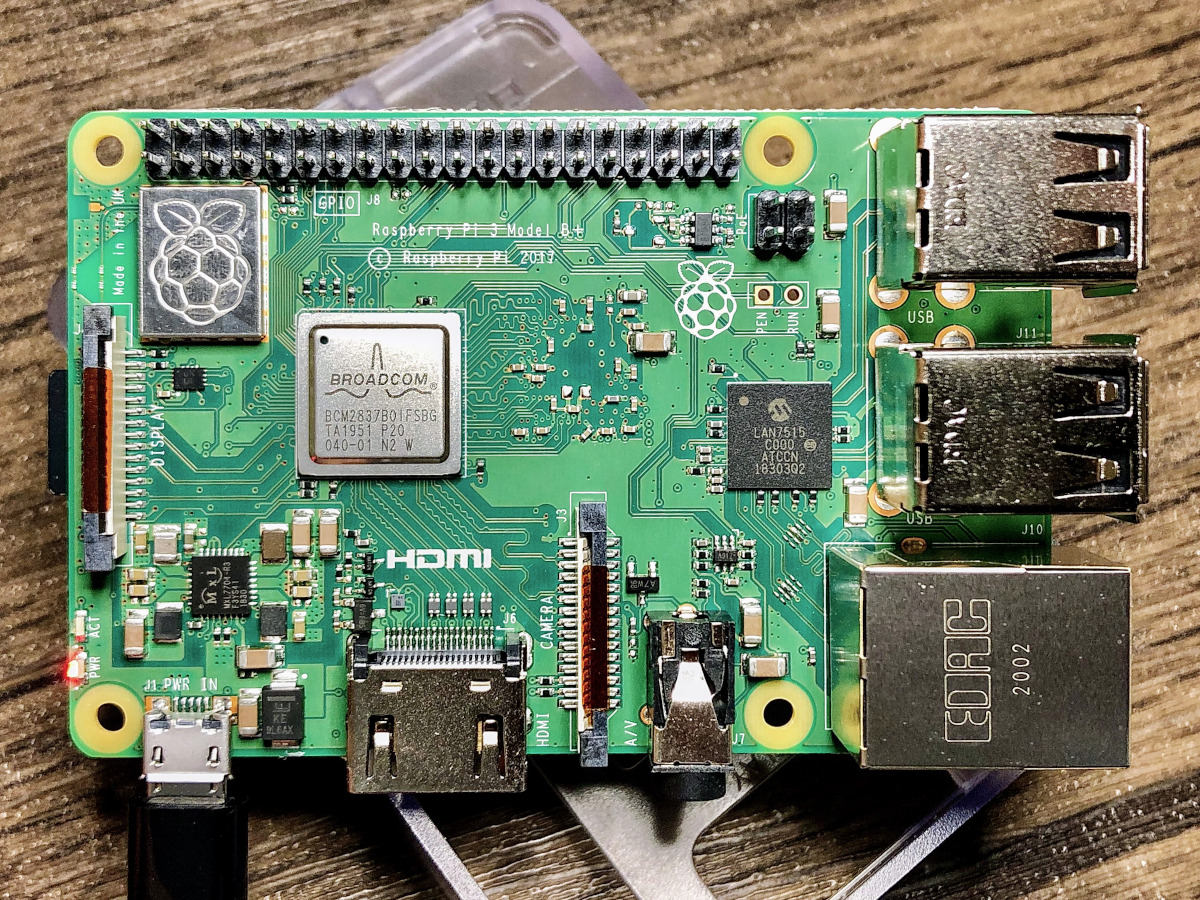
I have used an a third-generation Raspberry Pi 3 Model B+ single-board computer (SBC), to serve as an IoT Gateway. This Raspberry Pi model features a 1.4GHz Cortex-A53 (ARMv8) 64-bit quad-core processor System on a Chip (SoC), 1GB LPDDR2 SDRAM, dual-band wireless LAN, Bluetooth 4.2 BLE, and Gigabit Ethernet (Amazon: USD 42.99).
To follow along with the post, you could substitute the Raspberry Pi for any Linux-based machine to run the included sample Python script.
LoRa Transceiver Modules
To transmit the IoT sensor data between the IoT device, containing the embedded sensors, and the IoT gateway, I have used the REYAX RYLR896 LoRa transceiver module (Amazon: USD 19.50 x 2). The transceiver modules are commonly referred to as a universal asynchronous receiver-transmitter (UART). A UART is a computer hardware device for asynchronous serial communication in which the data format and transmission speeds are configurable.

According to the manufacturer, REYAX, the RYLR896 contains the Semtech SX1276 long-range, low power transceiver. The RYLR896 module provides ultra-long range spread spectrum communication and high interference immunity while minimizing current consumption. This transceiver operates at both the 868 and 915 MHz frequency ranges. We will be transmitting at 915 MHz for North America, in this post. Each RYLR896 module contains a small, PCB integrated, helical antenna.
Security
The RYLR896 is capable of the AES 128-bit data encryption. Using the Advanced Encryption Standard (AES), we will encrypt the data sent from the IoT device to the IoT gateway, using a 32 hex digit password (128 bits / 4 bits/hex digit = 32 hex digits). Using hexadecimal notation, the password is limited to digits 0–9 and characters A–F.
USB to TTL Serial Converter Adapter
Optionally, to configure, test, and debug the RYLR896 LoRa transceiver module directly from your laptop, you can use a USB to TTL serial converter adapter. I currently use the IZOKEE FT232RL FTDI USB to TTL Serial Converter Adapter Module for 3.3V and 5V (Amazon: USD 9.49 for 2). The 3.3V RYLR896 module easily connects to the USB to TTL Serial Converter Adapter using the TXD/TX, RXD/RX, VDD/VCC, and GND pins. We use serial communication to send and receive data through TX (transmit) and RX (receive) pins. The wiring is shown below: VDD to VCC, GND to GND, TXD to RX, and RXD to TX.

The FT232RL has support for baud rates up to 115,200 bps, which is the speed we will use to communicate with the RYLR896 module.
Arduino Sketch
For those not familiar with Arduino, a sketch is the name that Arduino uses for a program. It is the unit of code that is uploaded into non-volatile flash memory and runs on an Arduino board. The Arduino language is a set of C and C++ functions. All standard C and C++ constructs supported by the avr-g++ compiler should work in Arduino.
For this post, the sketch, lora_iot_demo.ino, contains all the code necessary to collect and securely transmit the environmental sensor data, including temperature, relative humidity, barometric pressure, RGB color, and ambient light intensity, using the LoRaWAN protocol. All code for this post, including the sketch, can be found on GitHub.
This file contains bidirectional Unicode text that may be interpreted or compiled differently than what appears below. To review, open the file in an editor that reveals hidden Unicode characters.
Learn more about bidirectional Unicode characters
| /* | |
| Description: Transmits Arduino Nano 33 BLE Sense sensor telemetry over LoRaWAN, | |
| including temperature, humidity, barometric pressure, and color, | |
| using REYAX RYLR896 transceiver modules | |
| http://reyax.com/wp-content/uploads/2020/01/Lora-AT-Command-RYLR40x_RYLR89x_EN.pdf | |
| Author: Gary Stafford | |
| */ | |
| #include <Arduino_HTS221.h> | |
| #include <Arduino_LPS22HB.h> | |
| #include <Arduino_APDS9960.h> | |
| const int UPDATE_FREQUENCY = 5000; // update frequency in ms | |
| const float CALIBRATION_FACTOR = -4.0; // temperature calibration factor (Celsius) | |
| const int ADDRESS = 116; | |
| const int NETWORK_ID = 6; | |
| const String PASSWORD = "92A0ECEC9000DA0DCF0CAAB0ABA2E0EF"; | |
| const String DELIMITER = "|"; | |
| void setup() | |
| { | |
| Serial.begin(9600); | |
| Serial1.begin(115200); // default baud rate of module is 115200 | |
| delay(1000); // wait for LoRa module to be ready | |
| // needs all need to be same for receiver and transmitter | |
| Serial1.print((String)"AT+ADDRESS=" + ADDRESS + "\r\n"); | |
| delay(200); | |
| Serial1.print((String)"AT+NETWORKID=" + NETWORK_ID + "\r\n"); | |
| delay(200); | |
| Serial1.print("AT+CPIN=" + PASSWORD + "\r\n"); | |
| delay(200); | |
| Serial1.print("AT+CPIN?\r\n"); // confirm password is set | |
| if (!HTS.begin()) | |
| { // initialize HTS221 sensor | |
| Serial.println("Failed to initialize humidity temperature sensor!"); | |
| while (1); | |
| } | |
| if (!BARO.begin()) | |
| { // initialize LPS22HB sensor | |
| Serial.println("Failed to initialize pressure sensor!"); | |
| while (1); | |
| } | |
| // avoid bad readings to start bug | |
| // https://forum.arduino.cc/index.php?topic=660360.0 | |
| BARO.readPressure(); | |
| delay(1000); | |
| if (!APDS.begin()) | |
| { // initialize APDS9960 sensor | |
| Serial.println("Failed to initialize color sensor!"); | |
| while (1); | |
| } | |
| } | |
| void loop() | |
| { | |
| updateReadings(); | |
| delay(UPDATE_FREQUENCY); | |
| } | |
| void updateReadings() | |
| { | |
| float temperature = getTemperature(CALIBRATION_FACTOR); | |
| float humidity = getHumidity(); | |
| float pressure = getPressure(); | |
| int colors[4]; | |
| getColor(colors); | |
| String payload = buildPayload(temperature, humidity, pressure, colors); | |
| // Serial.println("Payload: " + payload); // display the payload for debugging | |
| Serial1.print(payload); // send the payload over LoRaWAN WiFi | |
| displayResults(temperature, humidity, pressure, colors); // display the results for debugging | |
| } | |
| float getTemperature(float calibration) | |
| { | |
| return HTS.readTemperature() + calibration; | |
| } | |
| float getHumidity() | |
| { | |
| return HTS.readHumidity(); | |
| } | |
| float getPressure() | |
| { | |
| return BARO.readPressure(); | |
| } | |
| void getColor(int c[]) | |
| { | |
| // check if a color reading is available | |
| while (!APDS.colorAvailable()) | |
| { | |
| delay(5); | |
| } | |
| int r, g, b, a; | |
| APDS.readColor(r, g, b, a); | |
| c[0] = r; | |
| c[1] = g; | |
| c[2] = b; | |
| c[3] = a; | |
| } | |
| void displayResults(float t, float h, float p, int c[]) | |
| { | |
| Serial.print("Temperature: "); | |
| Serial.println(t); | |
| Serial.print("Humidity: "); | |
| Serial.println(h); | |
| Serial.print("Pressure: "); | |
| Serial.println(p); | |
| Serial.print("Color (r, g, b, a): "); | |
| Serial.print(c[0]); | |
| Serial.print(", "); | |
| Serial.print(c[1]); | |
| Serial.print(", "); | |
| Serial.print(c[2]); | |
| Serial.print(", "); | |
| Serial.println(c[3]); | |
| Serial.println("———-"); | |
| } | |
| String buildPayload(float t, float h, float p, int c[]) | |
| { | |
| String readings = ""; | |
| readings += t; | |
| readings += DELIMITER; | |
| readings += h; | |
| readings += DELIMITER; | |
| readings += p; | |
| readings += DELIMITER; | |
| readings += c[0]; | |
| readings += DELIMITER; | |
| readings += c[1]; | |
| readings += DELIMITER; | |
| readings += c[2]; | |
| readings += DELIMITER; | |
| readings += c[3]; | |
| String payload = ""; | |
| payload += "AT+SEND="; | |
| payload += ADDRESS; | |
| payload += ","; | |
| payload += readings.length(); | |
| payload += ","; | |
| payload += readings; | |
| payload += "\r\n"; | |
| return payload; | |
| } |
AT Commands
Communications with the RYLR896’s long-range modem is done using AT commands. AT commands are instructions used to control a modem. AT is the abbreviation of ATtention. Every command line starts with “AT”. That is why modem commands are called AT commands, according to Developer’s Home. A complete list of AT commands can be downloaded as a PDF from the RYLR896 product page.
To efficiently transmit the environmental sensor data from the IoT sensor to the IoT gateway, the sketch concatenates the sensor values together in a single string. The string will be incorporated into AT command to send the data to the RYLR896 LoRa transceiver module. To make it easier to parse the sensor data on the IoT gateway, we will delimit the sensor values with a pipe (|), as opposed to a comma. The maximum length of the payload (sensor data) is 240 bytes.
Below, we see an example of an AT command used to send the sensor data from the IoT sensor and the corresponding unencrypted data received by the IoT gateway. Both strings contain the LoRa transmitter Address ID, payload length, and the payload. The data received by the IoT gateway also contains the Received signal strength indicator (RSSI), and Signal-to-noise ratio (SNR).

Configure, Test, and Debug
As discussed earlier, to configure, test, and debug the RYLR896 LoRa transceiver modules without the use of the IoT gateway, you can use a USB to TTL serial converter adapter. The sketch is loaded on the Arduino Sense (the IoT device) and actively transmits data through one of the RYLR896 modules (shown below right). The other RYLR896 module is connected to your laptop’s USB port, via the USB to TTL serial converter adapter (shown below left). Using a terminal and the screen command, or the Arduino desktop application’s Serial Terminal, we can receive the sensor data from the Arduino Sense.

Using a terminal on your laptop, we first need to locate the correct virtual console (aka virtual terminal). On Linux or Mac, the virtual consoles are represented by device special files, such as /dev/tty1, /dev/tty2, and so forth. To find the virtual console for the USB to TTL serial converter adapter plugged into the laptop, use the following command.
ls -alh /dev/tty.*
We should see a virtual console with a name similar to /dev/tty.usbserial-.
... /dev/tty.Bluetooth-Incoming-Port
... /dev/tty.GarysBoseQC35II-SPPDev
... /dev/tty.a483e767cbac-Bluetooth-
... /dev/tty.usbserial-A50285BI
To connect to the RYLR896 module via the USB to TTL serial converter adapter, using the virtual terminal, we use the screen command and connect at a baud rate of 115,200 bps.
screen /dev/tty.usbserial-A50285BI 115200
If everything is configured and working correctly, we should see data being transmitted from the Arduino Sense and received by the local machine, at five second intervals. Each line of unencrypted data transmitted will look similar to the following, +RCV=116,25,22.18|41.57|99.74|2343|1190|543|4011,-34,47. In the example below, the AES 128-bit data encryption is not enabled on the Arduino, yet. With encryption turned on the sensor data (the payload) would appear garbled.

Even easier than the screen command, we can also use the Arduino desktop application’s Serial Terminal, as shown in the following short screen recording. Select the correct Port (virtual console) from the Tools menu and open the Serial Terminal. Since the transmitted data should be secured using AES 128-bit data encryption, we need to send an AT command (AT+CPIN) containing the transceiver module’s common password, to correctly decrypt the data on the receiving device (e.g., AT+CPIN=92A0ECEC9000DA0DCF0CAAB0ABA2E0EF).
Receiving Data on IoT Gateway
The Raspberry Pi will act as an IoT gateway, receiving the environmental sensor data from the IoT device, the Arduino. The Raspberry Pi will run a Python script, rasppi_lora_receiver.py, which will receive and decrypt the data payload, parse the sensor values, and display the values in the terminal. The script uses the pyserial, the Python Serial Port Extension. This Python module encapsulates the access for the serial port.
This file contains bidirectional Unicode text that may be interpreted or compiled differently than what appears below. To review, open the file in an editor that reveals hidden Unicode characters.
Learn more about bidirectional Unicode characters
| import logging | |
| import time | |
| from argparse import ArgumentParser | |
| from datetime import datetime | |
| import serial | |
| from colr import color as colr | |
| # LoRaWAN IoT Sensor Demo | |
| # Using REYAX RYLR896 transceiver modules | |
| # Author: Gary Stafford | |
| # Requirements: python3 -m pip install –user -r requirements.txt | |
| # To Run: python3 ./rasppi_lora_receiver.py –tty /dev/ttyAMA0 –baud-rate 115200 | |
| # constants | |
| ADDRESS = 116 | |
| NETWORK_ID = 6 | |
| PASSWORD = "92A0ECEC9000DA0DCF0CAAB0ABA2E0EF" | |
| def main(): | |
| logging.basicConfig(filename='output.log', filemode='w', level=logging.DEBUG) | |
| args = get_args() # get args | |
| payload = "" | |
| print("Connecting to REYAX RYLR896 transceiver module…") | |
| serial_conn = serial.Serial( | |
| port=args.tty, | |
| baudrate=int(args.baud_rate), | |
| timeout=5, | |
| parity=serial.PARITY_NONE, | |
| stopbits=serial.STOPBITS_ONE, | |
| bytesize=serial.EIGHTBITS | |
| ) | |
| if serial_conn.isOpen(): | |
| set_lora_config(serial_conn) | |
| check_lora_config(serial_conn) | |
| while True: | |
| serial_payload = serial_conn.readline() # read data from serial port | |
| if len(serial_payload) > 0: | |
| try: | |
| payload = serial_payload.decode(encoding="utf-8") | |
| except UnicodeDecodeError: # receiving corrupt data? | |
| logging.error("UnicodeDecodeError: {}".format(serial_payload)) | |
| payload = payload[:-2] | |
| try: | |
| data = parse_payload(payload) | |
| print("\n———-") | |
| print("Timestamp: {}".format(datetime.now())) | |
| print("Payload: {}".format(payload)) | |
| print("Sensor Data: {}".format(data)) | |
| display_temperature(data[0]) | |
| display_humidity(data[1]) | |
| display_pressure(data[2]) | |
| display_color(data[3], data[4], data[5], data[6]) | |
| except IndexError: | |
| logging.error("IndexError: {}".format(payload)) | |
| except ValueError: | |
| logging.error("ValueError: {}".format(payload)) | |
| # time.sleep(2) # transmission frequency set on IoT device | |
| def eight_bit_color(value): | |
| return int(round(value / (4097 / 255), 0)) | |
| def celsius_to_fahrenheit(value): | |
| return (value * 1.8) + 32 | |
| def display_color(r, g, b, a): | |
| print("12-bit Color values (r,g,b,a): {},{},{},{}".format(r, g, b, a)) | |
| r = eight_bit_color(r) | |
| g = eight_bit_color(g) | |
| b = eight_bit_color(b) | |
| a = eight_bit_color(a) # ambient light intensity | |
| print(" 8-bit Color values (r,g,b,a): {},{},{},{}".format(r, g, b, a)) | |
| print("RGB Color") | |
| print(colr("\t\t", fore=(127, 127, 127), back=(r, g, b))) | |
| print("Light Intensity") | |
| print(colr("\t\t", fore=(127, 127, 127), back=(a, a, a))) | |
| def display_pressure(value): | |
| print("Barometric Pressure: {} kPa".format(round(value, 2))) | |
| def display_humidity(value): | |
| print("Humidity: {}%".format(round(value, 2))) | |
| def display_temperature(value): | |
| temperature = celsius_to_fahrenheit(value) | |
| print("Temperature: {}°F".format(round(temperature, 2))) | |
| def get_args(): | |
| arg_parser = ArgumentParser(description="BLE IoT Sensor Demo") | |
| arg_parser.add_argument("–tty", required=True, help="serial tty", default="/dev/ttyAMA0") | |
| arg_parser.add_argument("–baud-rate", required=True, help="serial baud rate", default=1152000) | |
| args = arg_parser.parse_args() | |
| return args | |
| def parse_payload(payload): | |
| # input: +RCV=116,29,23.94|37.71|99.89|16|38|53|80,-61,56 | |
| # output: [23.94, 37.71, 99.89, 16.0, 38.0, 53.0, 80.0] | |
| payload = payload.split(",") | |
| payload = payload[2].split("|") | |
| payload = [float(i) for i in payload] | |
| return payload | |
| def set_lora_config(serial_conn): | |
| # configures the REYAX RYLR896 transceiver module | |
| serial_conn.write(str.encode("AT+ADDRESS=" + str(ADDRESS) + "\r\n")) | |
| serial_payload = (serial_conn.readline())[:-2] | |
| print("Address set?", serial_payload.decode(encoding="utf-8")) | |
| serial_conn.write(str.encode("AT+NETWORKID=" + str(NETWORK_ID) + "\r\n")) | |
| serial_payload = (serial_conn.readline())[:-2] | |
| print("Network Id set?", serial_payload.decode(encoding="utf-8")) | |
| serial_conn.write(str.encode("AT+CPIN=" + PASSWORD + "\r\n")) | |
| time.sleep(1) | |
| serial_payload = (serial_conn.readline())[:-2] | |
| print("AES-128 password set?", serial_payload.decode(encoding="utf-8")) | |
| def check_lora_config(serial_conn): | |
| serial_conn.write(str.encode("AT?\r\n")) | |
| serial_payload = (serial_conn.readline())[:-2] | |
| print("Module responding?", serial_payload.decode(encoding="utf-8")) | |
| serial_conn.write(str.encode("AT+ADDRESS?\r\n")) | |
| serial_payload = (serial_conn.readline())[:-2] | |
| print("Address:", serial_payload.decode(encoding="utf-8")) | |
| serial_conn.write(str.encode("AT+NETWORKID?\r\n")) | |
| serial_payload = (serial_conn.readline())[:-2] | |
| print("Network id:", serial_payload.decode(encoding="utf-8")) | |
| serial_conn.write(str.encode("AT+IPR?\r\n")) | |
| serial_payload = (serial_conn.readline())[:-2] | |
| print("UART baud rate:", serial_payload.decode(encoding="utf-8")) | |
| serial_conn.write(str.encode("AT+BAND?\r\n")) | |
| serial_payload = (serial_conn.readline())[:-2] | |
| print("RF frequency", serial_payload.decode(encoding="utf-8")) | |
| serial_conn.write(str.encode("AT+CRFOP?\r\n")) | |
| serial_payload = (serial_conn.readline())[:-2] | |
| print("RF output power", serial_payload.decode(encoding="utf-8")) | |
| serial_conn.write(str.encode("AT+MODE?\r\n")) | |
| serial_payload = (serial_conn.readline())[:-2] | |
| print("Work mode", serial_payload.decode(encoding="utf-8")) | |
| serial_conn.write(str.encode("AT+PARAMETER?\r\n")) | |
| serial_payload = (serial_conn.readline())[:-2] | |
| print("RF parameters", serial_payload.decode(encoding="utf-8")) | |
| serial_conn.write(str.encode("AT+CPIN?\r\n")) | |
| serial_payload = (serial_conn.readline())[:-2] | |
| print("AES128 password of the network", | |
| serial_payload.decode(encoding="utf-8")) | |
| if __name__ == "__main__": | |
| main() |
Prior to running the Python script, we can test and debug the connection from the Arduino Sense to the Raspberry Pi using a general application such as Minicom. Minicom is a text-based modem control and terminal emulator program. To install Minicom on the Raspberry Pi, use the following command.
sudo apt-get install minicom
To run Minicom or the Python script, we will need to know the virtual console of the serial connection (Serial1 in the script) used to communicate with the RYLR896 module, wired to the Raspberry Pi. This can found using the following command.
dmesg | grep -E --color 'serial|tty'
Search for a line, similar to the last line, shown below. Note the name of the virtual console, in my case, ttyAMA0.
[    0.000000] Kernel command line: coherent_pool=1M bcm2708_fb.fbwidth=656 bcm2708_fb.fbheight=416 bcm2708_fb.fbswap=1 vc_mem.mem_base=0x1ec00000 vc_mem.mem_size=0x20000000  dwc_otg.lpm_enable=0 console=tty1 root=PARTUUID=509d1565-02 rootfstype=ext4 elevator=deadline fsck.repair=yes rootwait quiet splash plymouth.ignore-serial-consoles
[    0.000637] console [tty1] enabled
[    0.863147] uart-pl011 20201000.serial: cts_event_workaround enabled
[    0.863289] 20201000.serial: ttyAMA0 at MMIO 0x20201000 (irq = 81, base_baud = 0) is a PL011 rev2
To view the data received from the Arduino Sense, using Minicom, use the following command, substituting the virtual console value, found above.
minicom -b 115200 -o -D /dev/ttyAMA0
If successful, we should see output similar to the lower right terminal window. Data is being transmitted by the Arduino Sense and being received by the Raspberry Pi, via LoRaWAN. In the below example, the AES 128-bit data encryption is not enabled on the Arduino, yet. With encryption turned on the sensor data (the payload) would appear garbled.

IoT Gateway Python Script
To run the Python script on the Raspberry Pi, use the following command, substituting the name of the virtual console (e.g., /dev/ttyAMA0).
python3 ./rasppi_lora_receiver.py \
  --tty /dev/ttyAMA0 --baud-rate 115200
The script starts by configuring the RYLR896 and outputting that configuration to the terminal. If successful, we should see the following informational output.
Connecting to REYAX RYLR896 transceiver module...

Address set? +OK
Network Id set? +OK
AES-128 password set? +OK
Module responding? +OK

Address: +ADDRESS=116
Firmware version: +VER=RYLR89C_V1.2.7
Network Id: +NETWORKID=6
UART baud rate: +IPR=115200
RF frequency +BAND=915000000
RF output power +CRFOP=15
Work mode +MODE=0
RF parameters +PARAMETER=12,7,1,4
AES-128 password of the network +CPIN=92A0ECEC9000DA0DCF0CAAB0ABA2E0EF
Once configured, the script will receive the data from the Arduino Sense, decrypt the data, parse the sensor values, and format and display the values within the terminal.
The following screen recording shows a parallel view of both the Arduino Serial Monitor (upper right window) and the Raspberry Pi’s terminal output (lower right window). The Raspberry Pi (receiver) receives data from the Arduino (transmitter). The Raspberry Pi successfully reads, decrypts, interprets, and displays the sensor data, including displaying color swatches for the RGB and light intensity sensor readings.
Conclusion
In this post, we explored the use of the LoRa and LoRaWAN protocols to transmit environmental sensor data from an IoT device to an IoT gateway. Given its low energy consumption, long-distance transmission capabilities, and well-developed protocols, LoRaWAN is an ideal long-range wireless protocol for IoT devices.
This blog represents my own viewpoints and not of my employer, Amazon Web Services (AWS). All product names, logos, and brands are the property of their respective owners.
BLE and GATT for IoT: Getting Started with Bluetooth Low Energy and the Generic Attribute Profile Specification for IoT
Posted by Gary A. Stafford in C++ Development, Python, Raspberry Pi, Software Development, Technology Consulting on August 4, 2020
Introduction
According to Wikipedia, Bluetooth is a wireless technology standard used for exchanging data between fixed and mobile devices over short distances. Bluetooth Low Energy (Bluetooth LE or BLE) is a wireless personal area network (WPAN) technology designed and marketed by the Bluetooth Special Interest Group (Bluetooth SIG). According to the Bluetooth SIG, BLE is designed for very low power operation. BLE supports data rates from 125 Kb/s to 2 Mb/s, with multiple power levels from 1 milliwatt (mW) to 100 mW. Several key factors influence the effective range of a reliable Bluetooth connection, which can vary from a kilometer down to less than a meter. The newer generation Bluetooth 5 provides a theoretical 4x range improvement over Bluetooth 4.2, from approximately 200 feet (60 meters) to 800 feet (240 meters).
Wikipedia currently lists 36 definitions of Bluetooth profiles defined and adopted by the Bluetooth SIG, including the Generic Attribute Profile (GATT) Specification. According to the Bluetooth SIG, GATT is built on top of the Attribute Protocol (ATT) and establishes common operations and a framework for the data transported and stored by the ATT. GATT provides profile discovery and description services for the BLE protocol. It defines how ATT attributes are grouped together into sets to form services.
Given its low energy consumption and well-developed profiles, such as GATT, BLE is an ideal short-range wireless protocol for Internet of Things (IoT) devices, when compared to competing protocols, such as ZigBee, Bluetooth classic, and Wi-Fi. In this post, we will explore the use of BLE and the GATT specification to transmit environmental sensor data from an IoT Sensor to an IoT Gateway.
IoT Sensor
In this post, we will use an Arduino single-board microcontroller to serve as an IoT sensor, actually an array of sensors. The 3.3V AI-enabled Arduino Nano 33 BLE Sense board, released in August 2019, comes with the powerful nRF52840 processor from Nordic Semiconductors, a 32-bit ARM Cortex-M4 CPU running at 64 MHz, 1MB of CPU Flash Memory, 256KB of SRAM, and a NINA-B306 stand-alone Bluetooth 5 low energy module.
The Sense also contains an impressive array of embedded sensors:
- 9-axis Inertial Sensor (LSM9DS1): 3D digital linear acceleration sensor, a 3D digital
angular rate sensor, and a 3D digital magnetic sensor - Humidity and Temperature Sensor (HTS221): Capacitive digital sensor for relative humidity and temperature
- Barometric Sensor (LPS22HB): MEMS nano pressure sensor: 260–1260 hectopascal (hPa) absolute digital output barometer
- Microphone (MP34DT05): MEMS audio sensor omnidirectional digital microphone
- Gesture, Proximity, Light Color, and Light Intensity Sensor (APDS9960): Advanced Gesture detection, Proximity detection, Digital Ambient Light Sense (ALS), and Color Sense (RGBC).
The Sense is an excellent, low-cost single-board microcontroller for learning about collecting and transmitting IoT sensor data.
IoT Gateway
An IoT Gateway, according to TechTarget, is a physical device or software program that serves as the connection point between the Cloud and controllers, sensors, and intelligent devices. All data moving to the Cloud, or vice versa goes through the gateway, which can be either a dedicated hardware appliance or software program.

In this post, we will use a recent Raspberry Pi 3 Model B+ single-board computer (SBC), to serve as an IoT Gateway. This Raspberry Pi model features a 1.4GHz Cortex-A53 (ARMv8) 64-bit quad-core processor System on a Chip (SoC), 1GB LPDDR2 SDRAM, dual-band wireless LAN, Bluetooth 4.2 BLE, and Gigabit Ethernet. To follow along with the post, you could substitute the Raspberry Pi for any Linux-based machine to run the included sample Python script.
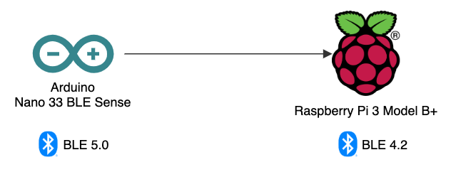
The Arduino will transmit IoT sensor telemetry, over BLE, to the Raspberry Pi. The Raspberry Pi, using Wi-Fi or Ethernet, is then able to securely transmit the sensor telemetry data to the Cloud. In Bluetooth terminology, the Bluetooth Peripheral device (aka GATT Server), which is the Arduino, will transmit data to the Bluetooth Central device (aka GATT Client), which is the Raspberry Pi.
Arduino Sketch
For those not familiar with Arduino, a sketch is the name that Arduino uses for a program. It is the unit of code that is uploaded into non-volatile flash memory and runs on an Arduino board. The Arduino language is a set of C/C++ functions. All standard C and C++ constructs supported by the avr-g++ compiler should work in Arduino.
For this post, the sketch, combo_sensor_ble.ino, contains all the code necessary to collect environmental sensor telemetry, including temperature, relative humidity, barometric pressure, and ambient light and RGB color. All code for this post, including the sketch, can be found on GitHub.
The sensor telemetry will be advertised by the Sense, over BLE, as a GATT Environmental Sensing Service (GATT Assigned Number 0x181A) with multiple GATT Characteristics. Each Characteristic represents a sensor reading and contains the most current sensor value(s), for example, Temperature (0x2A6E) or Humidity (0x2A6F).
Each GATT Characteristic defines how the data should be represented. To represent the data accurately, the sensor readings need to be modified. For example, using ArduinoHTS221 library, the temperature is captured with two decimal points of precision (e.g., 22.21 °C). However, the Temperature GATT Characteristic (0x2A6E) requires a signed 16-bit value (-32,768–32,767). To maintain precision, the captured value (e.g., 22.21 °C) is multiplied by 100 to convert it to an integer (e.g., 2221). The Raspberry Pi will then handle converting the value back to the original value with the correct precision.
The GATT specification has no current predefined Characteristic representing ambient light and RGB color. Therefore, I have created a custom Characteristic for the color values and assigned it a universally unique identifier (UUID).
According to the documentation, ambient light and RGB color are captured as 16-bit values (a range of 0–65,535). However, using the ArduinoAPDS9960 library, I have found the scale of the readings to be within a range of 0–4097. Without diving into the weeds, the maximum count (or saturation) value is variable. It can be calculated based upon the integration time and the size of the count register (e.g., 16-bits). The ADC integration time appears to be set to 10 ms in the library’s file, Arduino_APDS9960.cpp.
RGB values are typically represented as 8-bit color. We could convert the values to 8-bit before sending or handle it later on the Raspberry Pi IoT Gateway. For the sake of demonstration purposes versus data transfer efficiency, the sketch concatenates the 12-bit values together as a string (e.g., 4097,2811,1500,4097). The string will be converted from 12-bit to 8-bit on the Raspberry Pi (e.g., 255,175,93,255).
This file contains bidirectional Unicode text that may be interpreted or compiled differently than what appears below. To review, open the file in an editor that reveals hidden Unicode characters.
Learn more about bidirectional Unicode characters
| /* | |
| Description: Transmits Arduino Nano 33 BLE Sense sensor readings over BLE, | |
| including temperature, humidity, barometric pressure, and color, | |
| using the Bluetooth Generic Attribute Profile (GATT) Specification | |
| Author: Gary Stafford | |
| Reference: Source code adapted from `Nano 33 BLE Sense Getting Started` | |
| Adapted from Arduino BatteryMonitor example by Peter Milne | |
| */ | |
| /* | |
| Generic Attribute Profile (GATT) Specifications | |
| GATT Service: Environmental Sensing Service (ESS) Characteristics | |
| Temperature | |
| sint16 (decimalexponent -2) | |
| Unit is in degrees Celsius with a resolution of 0.01 degrees Celsius | |
| https://www.bluetooth.com/xml-viewer/?src=https://www.bluetooth.com/wp-content/uploads/Sitecore-Media-Library/Gatt/Xml/Characteristics/org.bluetooth.characteristic.temperature.xml | |
| Humidity | |
| uint16 (decimalexponent -2) | |
| Unit is in percent with a resolution of 0.01 percent | |
| https://www.bluetooth.com/xml-viewer/?src=https://www.bluetooth.com/wp-content/uploads/Sitecore-Media-Library/Gatt/Xml/Characteristics/org.bluetooth.characteristic.humidity.xml | |
| Barometric Pressure | |
| uint32 (decimalexponent -1) | |
| Unit is in pascals with a resolution of 0.1 Pa | |
| https://www.bluetooth.com/xml-viewer/?src=https://www.bluetooth.com/wp-content/uploads/Sitecore-Media-Library/Gatt/Xml/Characteristics/org.bluetooth.characteristic.pressure.xml | |
| */ | |
| #include <ArduinoBLE.h> | |
| #include <Arduino_HTS221.h> | |
| #include <Arduino_LPS22HB.h> | |
| #include <Arduino_APDS9960.h> | |
| const int UPDATE_FREQUENCY = 2000; // Update frequency in ms | |
| const float CALIBRATION_FACTOR = -4.0; // Temperature calibration factor (Celsius) | |
| int previousTemperature = 0; | |
| unsigned int previousHumidity = 0; | |
| unsigned int previousPressure = 0; | |
| String previousColor = ""; | |
| int r, g, b, a; | |
| long previousMillis = 0; // last time readings were checked, in ms | |
| BLEService environmentService("181A"); // Standard Environmental Sensing service | |
| BLEIntCharacteristic tempCharacteristic("2A6E", // Standard 16-bit Temperature characteristic | |
| BLERead | BLENotify); // Remote clients can read and get updates | |
| BLEUnsignedIntCharacteristic humidCharacteristic("2A6F", // Unsigned 16-bit Humidity characteristic | |
| BLERead | BLENotify); | |
| BLEUnsignedIntCharacteristic pressureCharacteristic("2A6D", // Unsigned 32-bit Pressure characteristic | |
| BLERead | BLENotify); // Remote clients can read and get updates | |
| BLECharacteristic colorCharacteristic("936b6a25-e503-4f7c-9349-bcc76c22b8c3", // Custom Characteristics | |
| BLERead | BLENotify, 24); // 1234,5678, | |
| BLEDescriptor colorLabelDescriptor("2901", "16-bit ints: r, g, b, a"); | |
| void setup() { | |
| Serial.begin(9600); // Initialize serial communication | |
| // while (!Serial); // only when connected to laptop | |
| if (!HTS.begin()) { // Initialize HTS221 sensor | |
| Serial.println("Failed to initialize humidity temperature sensor!"); | |
| while (1); | |
| } | |
| if (!BARO.begin()) { // Initialize LPS22HB sensor | |
| Serial.println("Failed to initialize pressure sensor!"); | |
| while (1); | |
| } | |
| // Avoid bad readings to start bug | |
| // https://forum.arduino.cc/index.php?topic=660360.0 | |
| BARO.readPressure(); | |
| delay(1000); | |
| if (!APDS.begin()) { // Initialize APDS9960 sensor | |
| Serial.println("Failed to initialize color sensor!"); | |
| while (1); | |
| } | |
| pinMode(LED_BUILTIN, OUTPUT); // Initialize the built-in LED pin | |
| if (!BLE.begin()) { // Initialize NINA B306 BLE | |
| Serial.println("starting BLE failed!"); | |
| while (1); | |
| } | |
| BLE.setLocalName("ArduinoNano33BLESense"); // Set name for connection | |
| BLE.setAdvertisedService(environmentService); // Advertise environment service | |
| environmentService.addCharacteristic(tempCharacteristic); // Add temperature characteristic | |
| environmentService.addCharacteristic(humidCharacteristic); // Add humidity characteristic | |
| environmentService.addCharacteristic(pressureCharacteristic); // Add pressure characteristic | |
| environmentService.addCharacteristic(colorCharacteristic); // Add color characteristic | |
| colorCharacteristic.addDescriptor(colorLabelDescriptor); // Add color characteristic descriptor | |
| BLE.addService(environmentService); // Add environment service | |
| tempCharacteristic.setValue(0); // Set initial temperature value | |
| humidCharacteristic.setValue(0); // Set initial humidity value | |
| pressureCharacteristic.setValue(0); // Set initial pressure value | |
| colorCharacteristic.setValue(""); // Set initial color value | |
| BLE.advertise(); // Start advertising | |
| Serial.print("Peripheral device MAC: "); | |
| Serial.println(BLE.address()); | |
| Serial.println("Waiting for connections…"); | |
| } | |
| void loop() { | |
| BLEDevice central = BLE.central(); // Wait for a BLE central to connect | |
| // If central is connected to peripheral | |
| if (central) { | |
| Serial.print("Connected to central MAC: "); | |
| Serial.println(central.address()); // Central's BT address: | |
| digitalWrite(LED_BUILTIN, HIGH); // Turn on the LED to indicate the connection | |
| while (central.connected()) { | |
| long currentMillis = millis(); | |
| // After UPDATE_FREQUENCY ms have passed, check temperature & humidity | |
| if (currentMillis – previousMillis >= UPDATE_FREQUENCY) { | |
| previousMillis = currentMillis; | |
| updateReadings(); | |
| } | |
| } | |
| digitalWrite(LED_BUILTIN, LOW); // When the central disconnects, turn off the LED | |
| Serial.print("Disconnected from central MAC: "); | |
| Serial.println(central.address()); | |
| } | |
| } | |
| int getTemperature(float calibration) { | |
| // Get calibrated temperature as signed 16-bit int for BLE characteristic | |
| return (int) (HTS.readTemperature() * 100) + (int) (calibration * 100); | |
| } | |
| unsigned int getHumidity() { | |
| // Get humidity as unsigned 16-bit int for BLE characteristic | |
| return (unsigned int) (HTS.readHumidity() * 100); | |
| } | |
| unsigned int getPressure() { | |
| // Get humidity as unsigned 32-bit int for BLE characteristic | |
| return (unsigned int) (BARO.readPressure() * 1000 * 10); | |
| } | |
| void getColor() { | |
| // check if a color reading is available | |
| while (!APDS.colorAvailable()) { | |
| delay(5); | |
| } | |
| // Get color as (4) unsigned 16-bit ints | |
| int tmp_r, tmp_g, tmp_b, tmp_a; | |
| APDS.readColor(tmp_r, tmp_g, tmp_b, tmp_a); | |
| r = tmp_r; | |
| g = tmp_g; | |
| b = tmp_b; | |
| a = tmp_a; | |
| } | |
| void updateReadings() { | |
| int temperature = getTemperature(CALIBRATION_FACTOR); | |
| unsigned int humidity = getHumidity(); | |
| unsigned int pressure = getPressure(); | |
| getColor(); | |
| if (temperature != previousTemperature) { // If reading has changed | |
| Serial.print("Temperature: "); | |
| Serial.println(temperature); | |
| tempCharacteristic.writeValue(temperature); // Update characteristic | |
| previousTemperature = temperature; // Save value | |
| } | |
| if (humidity != previousHumidity) { // If reading has changed | |
| Serial.print("Humidity: "); | |
| Serial.println(humidity); | |
| humidCharacteristic.writeValue(humidity); | |
| previousHumidity = humidity; | |
| } | |
| if (pressure != previousPressure) { // If reading has changed | |
| Serial.print("Pressure: "); | |
| Serial.println(pressure); | |
| pressureCharacteristic.writeValue(pressure); | |
| previousPressure = pressure; | |
| } | |
| // Get color reading everytime | |
| // e.g. "12345,45678,89012,23456" | |
| String stringColor = ""; | |
| stringColor += r; | |
| stringColor += ","; | |
| stringColor += g; | |
| stringColor += ","; | |
| stringColor += b; | |
| stringColor += ","; | |
| stringColor += a; | |
| if (stringColor != previousColor) { // If reading has changed | |
| byte bytes[stringColor.length() + 1]; | |
| stringColor.getBytes(bytes, stringColor.length() + 1); | |
| Serial.print("r, g, b, a: "); | |
| Serial.println(stringColor); | |
| colorCharacteristic.writeValue(bytes, sizeof(bytes)); | |
| previousColor = stringColor; | |
| } | |
| } |
Previewing and Debugging BLE Device Services
Before looking at the code running on the Raspberry Pi, we can use any number of mobile applications to preview and debug the Environmental Sensing service running on the Arduino and being advertised over BLE. A commonly recommended application is Nordic Semiconductor’s nRF Connect for Mobile, available on Google Play. I have found the Android version works better at correctly interpreting and displaying GATT Characteristic values than the iOS version of the app.
Below, we see a scan of my local vicinity for BLE devices being advertised, using the Android version of the nRF Connect mobile application. Note the BLE device, ArduinoNano33BLESense (indicated in red). Also, note the media access control address (MAC address) of that BLE device, in my case, d1:aa:89:0c:ee:82. The MAC address will be required later on the IoT Gateway.

Connecting to the device, we see three Services. The Environmental Sensing Service (indicated in red) contains the sensor readings.

Drilling down into the Environmental Sensing Service (0x181A), we see the four expected Characteristics: Temperature (0x2A6E), Humidity (0x2A6F), Pressure (0x2A6D), and Unknown Characteristic (936b6a25-e503-4f7c-9349-bcc76c22b8c3). Since nRF Connect cannot recognize the color sensor reading as a registered GATT Characteristic (no GATT Assigned Number), it is displayed as an Unknown Characteristic. Whereas the temperature, humidity, and pressure values (indicated in red) are interpreted and displayed correctly, the color sensor reading is left as raw hexadecimal text (e.g., 30-2c-30-2c-30-2c-30-00 or 0,0,0,0).

These results indicate everything is working as expected.
BLE Client Python Code
To act as the BLE Client (aka central device), the Raspberry Pi runs a Python script. The script, rasppi_ble_receiver.py, uses the bluepy Python module for interfacing with BLE devices through Bluez, on Linux.
This file contains bidirectional Unicode text that may be interpreted or compiled differently than what appears below. To review, open the file in an editor that reveals hidden Unicode characters.
Learn more about bidirectional Unicode characters
| import sys | |
| import time | |
| from argparse import ArgumentParser | |
| from bluepy import btle # linux only (no mac) | |
| from colr import color as colr | |
| # BLE IoT Sensor Demo | |
| # Author: Gary Stafford | |
| # Reference: https://elinux.org/RPi_Bluetooth_LE | |
| # Requirements: python3 -m pip install –user -r requirements.txt | |
| # To Run: python3 ./rasppi_ble_receiver.py d1:aa:89:0c:ee:82 <- MAC address – change me! | |
| def main(): | |
| # get args | |
| args = get_args() | |
| print("Connecting…") | |
| nano_sense = btle.Peripheral(args.mac_address) | |
| print("Discovering Services…") | |
| _ = nano_sense.services | |
| environmental_sensing_service = nano_sense.getServiceByUUID("181A") | |
| print("Discovering Characteristics…") | |
| _ = environmental_sensing_service.getCharacteristics() | |
| while True: | |
| print("\n") | |
| read_temperature(environmental_sensing_service) | |
| read_humidity(environmental_sensing_service) | |
| read_pressure(environmental_sensing_service) | |
| read_color(environmental_sensing_service) | |
| # time.sleep(2) # transmission frequency set on IoT device | |
| def byte_array_to_int(value): | |
| # Raw data is hexstring of int values, as a series of bytes, in little endian byte order | |
| # values are converted from bytes -> bytearray -> int | |
| # e.g., b'\xb8\x08\x00\x00' -> bytearray(b'\xb8\x08\x00\x00') -> 2232 | |
| # print(f"{sys._getframe().f_code.co_name}: {value}") | |
| value = bytearray(value) | |
| value = int.from_bytes(value, byteorder="little") | |
| return value | |
| def split_color_str_to_array(value): | |
| # e.g., b'2660,2059,1787,4097\x00' -> 2660,2059,1787,4097 -> | |
| # [2660, 2059, 1787, 4097] -> 166.0,128.0,111.0,255.0 | |
| # print(f"{sys._getframe().f_code.co_name}: {value}") | |
| # remove extra bit on end ('\x00') | |
| value = value[0:-1] | |
| # split r, g, b, a values into array of 16-bit ints | |
| values = list(map(int, value.split(","))) | |
| # convert from 16-bit ints (2^16 or 0-65535) to 8-bit ints (2^8 or 0-255) | |
| # values[:] = [int(v) % 256 for v in values] | |
| # actual sensor is reading values are from 0 – 4097 | |
| print(f"12-bit Color values (r,g,b,a): {values}") | |
| values[:] = [round(int(v) / (4097 / 255), 0) for v in values] | |
| return values | |
| def byte_array_to_char(value): | |
| # e.g., b'2660,2058,1787,4097\x00' -> 2659,2058,1785,4097 | |
| value = value.decode("utf-8") | |
| return value | |
| def decimal_exponent_two(value): | |
| # e.g., 2350 -> 23.5 | |
| return value / 100 | |
| def decimal_exponent_one(value): | |
| # e.g., 988343 -> 98834.3 | |
| return value / 10 | |
| def pascals_to_kilopascals(value): | |
| # 1 Kilopascal (kPa) is equal to 1000 pascals (Pa) | |
| # to convert kPa to pascal, multiply the kPa value by 1000 | |
| # 98834.3 -> 98.8343 | |
| return value / 1000 | |
| def celsius_to_fahrenheit(value): | |
| return (value * 1.8) + 32 | |
| def read_color(service): | |
| color_char = service.getCharacteristics("936b6a25-e503-4f7c-9349-bcc76c22b8c3")[0] | |
| color = color_char.read() | |
| color = byte_array_to_char(color) | |
| color = split_color_str_to_array(color) | |
| print(f" 8-bit Color values (r,g,b,a): {color[0]},{color[1]},{color[2]},{color[3]}") | |
| print("RGB Color") | |
| print(colr('\t\t', fore=(127, 127, 127), back=(color[0], color[1], color[2]))) | |
| print("Light Intensity") | |
| print(colr('\t\t', fore=(127, 127, 127), back=(color[3], color[3], color[3]))) | |
| def read_pressure(service): | |
| pressure_char = service.getCharacteristics("2A6D")[0] | |
| pressure = pressure_char.read() | |
| pressure = byte_array_to_int(pressure) | |
| pressure = decimal_exponent_one(pressure) | |
| pressure = pascals_to_kilopascals(pressure) | |
| print(f"Barometric Pressure: {round(pressure, 2)} kPa") | |
| def read_humidity(service): | |
| humidity_char = service.getCharacteristics("2A6F")[0] | |
| humidity = humidity_char.read() | |
| humidity = byte_array_to_int(humidity) | |
| humidity = decimal_exponent_two(humidity) | |
| print(f"Humidity: {round(humidity, 2)}%") | |
| def read_temperature(service): | |
| temperature_char = service.getCharacteristics("2A6E")[0] | |
| temperature = temperature_char.read() | |
| temperature = byte_array_to_int(temperature) | |
| temperature = decimal_exponent_two(temperature) | |
| temperature = celsius_to_fahrenheit(temperature) | |
| print(f"Temperature: {round(temperature, 2)}°F") | |
| def get_args(): | |
| arg_parser = ArgumentParser(description="BLE IoT Sensor Demo") | |
| arg_parser.add_argument('mac_address', help="MAC address of device to connect") | |
| args = arg_parser.parse_args() | |
| return args | |
| if __name__ == "__main__": | |
| main() |
To run the Python script, execute the following command, substituting the MAC address argument for your own BLE device’s advertised MAC address.
python3 ./rasppi_ble_receiver.py d1:aa:89:0c:ee:82
Unlike the nRF Connect app, the bluepy Python module is not capable of correctly interpreting and displaying the GATT Characteristic values. Hence, the script takes the raw, incoming hexadecimal text from the Arduino and coerces it to the correct values. For example, a temperature reading must be transformed from bytes, b'\xb8\x08\x00\x00', to a byte array, bytearray(b'\xb8\x08\x00\x00'), then to an integer, 2232, then to a decimal, 22.32, and finally to the Fahrenheit scale, 72.18°F.
Sensor readings are retrieved from the BLE device every two seconds. In addition to displaying the numeric sensor readings, the Python script also displays a color swatch of the 8-bit RGB color, as well as a grayscale swatch representing the light intensity using the colr Python module.

The following screen recording shows a parallel view of both the Arduino Serial Monitor and the Raspberry Pi’s terminal output. The Raspberry Pi (central device) connects to the Arduino (peripheral device) when the Python script is started. The Raspberry Pi successfully reads and interprets the telemetry data from the Environmental Sensing Service.
Conclusion
In this post, we explored the use of BLE and the GATT specification to transmit environmental sensor data from a peripheral device to a central device. Given its low energy consumption and well-developed profiles, such as GATT, Bluetooth Low Energy (BLE) is an ideal short-range wireless protocol for IoT devices.
This blog represents my own viewpoints and not of my employer, Amazon Web Services.
Object Tracking on the Raspberry Pi with C++, OpenCV, and cvBlob
Posted by Gary A. Stafford in Bash Scripting, C++ Development, Raspberry Pi on February 9, 2013
Use C++ with OpenCV and cvBlob to perform image processing and object tracking on the Raspberry Pi, using a webcam.
Source code and compiled samples are now available on GitHub. The below post describes the original code on the ‘Master’ branch. As of May 2014, there is a revised and improved version of the project on the ‘rev05_2014’ branch, on GitHub. The README.md details the changes and also describes how to install OpenCV, cvBlob, and all dependencies!
Introduction
As part of a project with a local FIRST Robotics Competition (FRC) Team, I’ve been involved in developing a Computer Vision application for use on the Raspberry Pi. Our FRC team’s goal is to develop an object tracking and target acquisition application that could be run on the Raspberry Pi, as opposed to the robot’s primary embedded processor, a National Instrument’s NI cRIO-FRC II. We chose to work in C++ for its speed, We also decided to test two popular open-source Computer Vision (CV) libraries, OpenCV and cvBlob.
Due to its single ARM1176JZF-S 700 MHz ARM processor, a significant limitation of the Raspberry Pi is the ability to perform complex operations in real-time, such as image processing. In an earlier post, I discussed Motion to detect motion with a webcam on the Raspberry Pi. Although the Raspberry Pi was capable of running Motion, it required a greatly reduced capture size and frame-rate. And even then, the Raspberry Pi’s ability to process the webcam’s feed was very slow. I had doubts it would be able to meet the processor-intense requirements of this project.
Development for the Raspberry Pi
Using C++ in NetBeans 7.2.1 on Ubuntu 12.04.1 LTS and 12.10, I wrote several small pieces of code to demonstrate the Raspberry Pi’s ability to perform basic image processing and object tracking. Parts of the follow code are based on several OpenCV and cvBlob code examples, found in my research. Many of those examples are linked on the end of this article. Examples of cvBlob are especially hard to find.
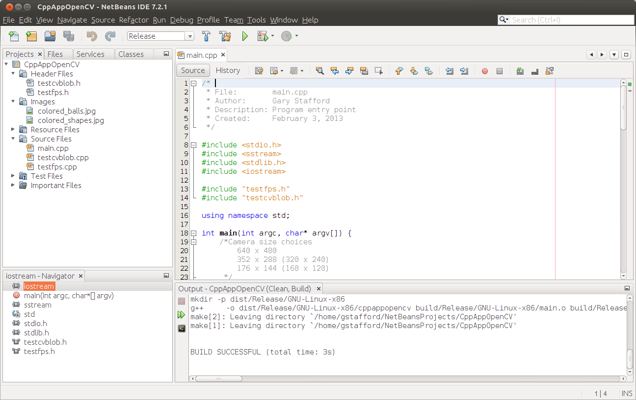
Project in NetBeans
The Code
There are five files: ‘main.cpp’, ‘testfps.cpp (testfps.h)’, and ‘testcvblob.cpp (testcvblob.h)’. The main.cpp file’s main method calls the test methods in the other two files. The cvBlob library only works with the pre-OpenCV 2.0. Therefore, I wrote all the code using the older objects and methods. The code is not written using the latest OpenCV 2.0 conventions. For example, cvBlob uses 1.0’s ‘IplImage’ image type instead 2.0’s newer ‘CvMat’ image type. My next projects is to re-write the cvBlob code to use OpenCV 2.0 conventions and/or find a newer library. The cvBlob library offered so many advantages, I felt not using the newer OpenCV 2.0 features was still worthwhile.
Main Program Method (main.cpp)
| /* | |
| * File: main.cpp | |
| * Author: Gary Stafford | |
| * Description: Program entry point | |
| * Created: February 3, 2013 | |
| */ | |
| #include <stdio.h> | |
| #include <sstream> | |
| #include <stdlib.h> | |
| #include <iostream> | |
| #include "testfps.hpp" | |
| #include "testcvblob.hpp" | |
| using namespace std; | |
| int main(int argc, char* argv[]) { | |
| int captureMethod = 0; | |
| int captureWidth = 0; | |
| int captureHeight = 0; | |
| if (argc == 4) { // user input parameters with call | |
| captureMethod = strtol(argv[1], NULL, 0); | |
| captureWidth = strtol(argv[2], NULL, 0); | |
| captureHeight = strtol(argv[3], NULL, 0); | |
| } else { // user did not input parameters with call | |
| cout << endl << "Demonstrations/Tests: " << endl; | |
| cout << endl << "(1) Test OpenCV - Show Webcam" << endl; | |
| cout << endl << "(2) Test OpenCV - No Webcam" << endl; | |
| cout << endl << "(3) Test cvBlob - Show Image" << endl; | |
| cout << endl << "(4) Test cvBlob - No Image" << endl; | |
| cout << endl << "(5) Test Blob Tracking - Show Webcam" << endl; | |
| cout << endl << "(6) Test Blob Tracking - No Webcam" << endl; | |
| cout << endl << "Input test # (1-6): "; | |
| cin >> captureMethod; | |
| // test 3 and 4 don't require width and height parameters | |
| if (captureMethod != 3 && captureMethod != 4) { | |
| cout << endl << "Input capture width (pixels): "; | |
| cin >> captureWidth; | |
| cout << endl << "Input capture height (pixels): "; | |
| cin >> captureHeight; | |
| cout << endl; | |
| if (!captureWidth > 0) { | |
| cout << endl << "Width value incorrect" << endl; | |
| return -1; | |
| } | |
| if (!captureHeight > 0) { | |
| cout << endl << "Height value incorrect" << endl; | |
| return -1; | |
| } | |
| } | |
| } | |
| switch (captureMethod) { | |
| case 1: | |
| TestFpsShowVideo(captureWidth, captureHeight); | |
| case 2: | |
| TestFpsNoVideo(captureWidth, captureHeight); | |
| break; | |
| case 3: | |
| DetectBlobsShowStillImage(); | |
| break; | |
| case 4: | |
| DetectBlobsNoStillImage(); | |
| break; | |
| case 5: | |
| DetectBlobsShowVideo(captureWidth, captureHeight); | |
| break; | |
| case 6: | |
| DetectBlobsNoVideo(captureWidth, captureHeight); | |
| break; | |
| default: | |
| break; | |
| } | |
| return 0; | |
| } |
Tests 1-2 (testcvblob.hpp)
| // -*- C++ -*- | |
| /* | |
| * File: testcvblob.hpp | |
| * Author: Gary Stafford | |
| * Created: February 3, 2013 | |
| */ | |
| #ifndef TESTCVBLOB_HPP | |
| #define TESTCVBLOB_HPP | |
| int DetectBlobsNoStillImage(); | |
| int DetectBlobsShowStillImage(); | |
| int DetectBlobsNoVideo(int captureWidth, int captureHeight); | |
| int DetectBlobsShowVideo(int captureWidth, int captureHeight); | |
| #endif /* TESTCVBLOB_HPP */ |
Tests 1-2 (testcvblob.cpp)
| /* | |
| * File: testcvblob.cpp | |
| * Author: Gary Stafford | |
| * Description: Track blobs using OpenCV and cvBlob | |
| * Created: February 3, 2013 | |
| */ | |
| #include <cv.h> | |
| #include <highgui.h> | |
| #include <cvblob.h> | |
| #include "testcvblob.hpp" | |
| using namespace cvb; | |
| using namespace std; | |
| // Test 3: OpenCV and cvBlob (w/ webcam feed) | |
| int DetectBlobsNoStillImage() { | |
| /// Variables ///////////////////////////////////////////////////////// | |
| CvSize imgSize; | |
| IplImage *image, *segmentated, *labelImg; | |
| CvBlobs blobs; | |
| unsigned int result = 0; | |
| /////////////////////////////////////////////////////////////////////// | |
| image = cvLoadImage("colored_balls.jpg"); | |
| if (image == NULL) { | |
| return -1; | |
| } | |
| imgSize = cvGetSize(image); | |
| cout << endl << "Width (pixels): " << image->width; | |
| cout << endl << "Height (pixels): " << image->height; | |
| cout << endl << "Channels: " << image->nChannels; | |
| cout << endl << "Bit Depth: " << image->depth; | |
| cout << endl << "Image Data Size (kB): " | |
| << image->imageSize / 1024 << endl << endl; | |
| segmentated = cvCreateImage(imgSize, 8, 1); | |
| cvInRangeS(image, CV_RGB(155, 0, 0), CV_RGB(255, 130, 130), segmentated); | |
| labelImg = cvCreateImage(cvGetSize(image), IPL_DEPTH_LABEL, 1); | |
| result = cvLabel(segmentated, labelImg, blobs); | |
| cvFilterByArea(blobs, 500, 1000000); | |
| cout << endl << "Blob Count: " << blobs.size(); | |
| cout << endl << "Pixels Labeled: " << result << endl << endl; | |
| cvReleaseBlobs(blobs); | |
| cvReleaseImage(&labelImg); | |
| cvReleaseImage(&segmentated); | |
| cvReleaseImage(&image); | |
| return 0; | |
| } | |
| // Test 4: OpenCV and cvBlob (w/o webcam feed) | |
| int DetectBlobsShowStillImage() { | |
| /// Variables ///////////////////////////////////////////////////////// | |
| CvSize imgSize; | |
| IplImage *image, *frame, *segmentated, *labelImg; | |
| CvBlobs blobs; | |
| unsigned int result = 0; | |
| bool quit = false; | |
| /////////////////////////////////////////////////////////////////////// | |
| cvNamedWindow("Processed Image", CV_WINDOW_AUTOSIZE); | |
| cvMoveWindow("Processed Image", 750, 100); | |
| cvNamedWindow("Image", CV_WINDOW_AUTOSIZE); | |
| cvMoveWindow("Image", 100, 100); | |
| image = cvLoadImage("colored_balls.jpg"); | |
| if (image == NULL) { | |
| return -1; | |
| } | |
| imgSize = cvGetSize(image); | |
| cout << endl << "Width (pixels): " << image->width; | |
| cout << endl << "Height (pixels): " << image->height; | |
| cout << endl << "Channels: " << image->nChannels; | |
| cout << endl << "Bit Depth: " << image->depth; | |
| cout << endl << "Image Data Size (kB): " | |
| << image->imageSize / 1024 << endl << endl; | |
| frame = cvCreateImage(imgSize, image->depth, image->nChannels); | |
| cvConvertScale(image, frame, 1, 0); | |
| segmentated = cvCreateImage(imgSize, 8, 1); | |
| cvInRangeS(image, CV_RGB(155, 0, 0), CV_RGB(255, 130, 130), segmentated); | |
| cvSmooth(segmentated, segmentated, CV_MEDIAN, 7, 7); | |
| labelImg = cvCreateImage(cvGetSize(frame), IPL_DEPTH_LABEL, 1); | |
| result = cvLabel(segmentated, labelImg, blobs); | |
| cvFilterByArea(blobs, 500, 1000000); | |
| cvRenderBlobs(labelImg, blobs, frame, frame, | |
| CV_BLOB_RENDER_BOUNDING_BOX | CV_BLOB_RENDER_TO_STD, 1.); | |
| cvShowImage("Image", frame); | |
| cvShowImage("Processed Image", segmentated); | |
| while (!quit) { | |
| char k = cvWaitKey(10)&0xff; | |
| switch (k) { | |
| case 27: | |
| case 'q': | |
| case 'Q': | |
| quit = true; | |
| break; | |
| } | |
| } | |
| cvReleaseBlobs(blobs); | |
| cvReleaseImage(&labelImg); | |
| cvReleaseImage(&segmentated); | |
| cvReleaseImage(&frame); | |
| cvReleaseImage(&image); | |
| cvDestroyAllWindows(); | |
| return 0; | |
| } | |
| // Test 5: Blob Tracking (w/ webcam feed) | |
| int DetectBlobsNoVideo(int captureWidth, int captureHeight) { | |
| /// Variables ///////////////////////////////////////////////////////// | |
| CvCapture *capture; | |
| CvSize imgSize; | |
| IplImage *image, *frame, *segmentated, *labelImg; | |
| int picWidth, picHeight; | |
| CvTracks tracks; | |
| CvBlobs blobs; | |
| CvBlob* blob; | |
| unsigned int result = 0; | |
| bool quit = false; | |
| /////////////////////////////////////////////////////////////////////// | |
| capture = cvCaptureFromCAM(-1); | |
| cvSetCaptureProperty(capture, CV_CAP_PROP_FRAME_WIDTH, captureWidth); | |
| cvSetCaptureProperty(capture, CV_CAP_PROP_FRAME_HEIGHT, captureHeight); | |
| cvGrabFrame(capture); | |
| image = cvRetrieveFrame(capture); | |
| if (image == NULL) { | |
| return -1; | |
| } | |
| imgSize = cvGetSize(image); | |
| cout << endl << "Width (pixels): " << image->width; | |
| cout << endl << "Height (pixels): " << image->height << endl << endl; | |
| frame = cvCreateImage(imgSize, image->depth, image->nChannels); | |
| while (!quit && cvGrabFrame(capture)) { | |
| image = cvRetrieveFrame(capture); | |
| cvConvertScale(image, frame, 1, 0); | |
| segmentated = cvCreateImage(imgSize, 8, 1); | |
| cvInRangeS(image, CV_RGB(155, 0, 0), CV_RGB(255, 130, 130), segmentated); | |
| //Can experiment either or both | |
| cvSmooth(segmentated, segmentated, CV_MEDIAN, 7, 7); | |
| cvSmooth(segmentated, segmentated, CV_GAUSSIAN, 9, 9); | |
| labelImg = cvCreateImage(cvGetSize(frame), IPL_DEPTH_LABEL, 1); | |
| result = cvLabel(segmentated, labelImg, blobs); | |
| cvFilterByArea(blobs, 500, 1000000); | |
| cvRenderBlobs(labelImg, blobs, frame, frame, 0x000f, 1.); | |
| cvUpdateTracks(blobs, tracks, 200., 5); | |
| cvRenderTracks(tracks, frame, frame, 0x000f, NULL); | |
| picWidth = frame->width; | |
| picHeight = frame->height; | |
| if (cvGreaterBlob(blobs)) { | |
| blob = blobs[cvGreaterBlob(blobs)]; | |
| cout << "Blobs found: " << blobs.size() << endl; | |
| cout << "Pixels labeled: " << result << endl; | |
| cout << "center-x: " << blob->centroid.x | |
| << " center-y: " << blob->centroid.y | |
| << endl; | |
| cout << "offset-x: " << ((picWidth / 2)-(blob->centroid.x)) | |
| << " offset-y: " << (picHeight / 2)-(blob->centroid.y) | |
| << endl; | |
| cout << "\n"; | |
| } | |
| char k = cvWaitKey(10)&0xff; | |
| switch (k) { | |
| case 27: | |
| case 'q': | |
| case 'Q': | |
| quit = true; | |
| break; | |
| } | |
| } | |
| cvReleaseBlobs(blobs); | |
| cvReleaseImage(&labelImg); | |
| cvReleaseImage(&segmentated); | |
| cvReleaseImage(&frame); | |
| cvReleaseImage(&image); | |
| cvDestroyAllWindows(); | |
| cvReleaseCapture(&capture); | |
| return 0; | |
| } | |
| // Test 6: Blob Tracking (w/o webcam feed) | |
| int DetectBlobsShowVideo(int captureWidth, int captureHeight) { | |
| /// Variables ///////////////////////////////////////////////////////// | |
| CvCapture *capture; | |
| CvSize imgSize; | |
| IplImage *image, *frame, *segmentated, *labelImg; | |
| CvPoint pt1, pt2, pt3, pt4, pt5, pt6; | |
| CvScalar red, green, blue; | |
| int picWidth, picHeight, thickness; | |
| CvTracks tracks; | |
| CvBlobs blobs; | |
| CvBlob* blob; | |
| unsigned int result = 0; | |
| bool quit = false; | |
| /////////////////////////////////////////////////////////////////////// | |
| cvNamedWindow("Processed Video Frames", CV_WINDOW_AUTOSIZE); | |
| cvMoveWindow("Processed Video Frames", 750, 400); | |
| cvNamedWindow("Webcam Preview", CV_WINDOW_AUTOSIZE); | |
| cvMoveWindow("Webcam Preview", 200, 100); | |
| capture = cvCaptureFromCAM(1); | |
| cvSetCaptureProperty(capture, CV_CAP_PROP_FRAME_WIDTH, captureWidth); | |
| cvSetCaptureProperty(capture, CV_CAP_PROP_FRAME_HEIGHT, captureHeight); | |
| cvGrabFrame(capture); | |
| image = cvRetrieveFrame(capture); | |
| if (image == NULL) { | |
| return -1; | |
| } | |
| imgSize = cvGetSize(image); | |
| cout << endl << "Width (pixels): " << image->width; | |
| cout << endl << "Height (pixels): " << image->height << endl << endl; | |
| frame = cvCreateImage(imgSize, image->depth, image->nChannels); | |
| while (!quit && cvGrabFrame(capture)) { | |
| image = cvRetrieveFrame(capture); | |
| cvFlip(image, image, 1); | |
| cvConvertScale(image, frame, 1, 0); | |
| segmentated = cvCreateImage(imgSize, 8, 1); | |
| //Blue paper | |
| cvInRangeS(image, CV_RGB(49, 69, 100), CV_RGB(134, 163, 216), segmentated); | |
| //Green paper | |
| //cvInRangeS(image, CV_RGB(45, 92, 76), CV_RGB(70, 155, 124), segmentated); | |
| //Can experiment either or both | |
| cvSmooth(segmentated, segmentated, CV_MEDIAN, 7, 7); | |
| cvSmooth(segmentated, segmentated, CV_GAUSSIAN, 9, 9); | |
| labelImg = cvCreateImage(cvGetSize(frame), IPL_DEPTH_LABEL, 1); | |
| result = cvLabel(segmentated, labelImg, blobs); | |
| cvFilterByArea(blobs, 500, 1000000); | |
| cvRenderBlobs(labelImg, blobs, frame, frame, CV_BLOB_RENDER_COLOR, 0.5); | |
| cvUpdateTracks(blobs, tracks, 200., 5); | |
| cvRenderTracks(tracks, frame, frame, CV_TRACK_RENDER_BOUNDING_BOX, NULL); | |
| red = CV_RGB(250, 0, 0); | |
| green = CV_RGB(0, 250, 0); | |
| blue = CV_RGB(0, 0, 250); | |
| thickness = 1; | |
| picWidth = frame->width; | |
| picHeight = frame->height; | |
| pt1 = cvPoint(picWidth / 2, 0); | |
| pt2 = cvPoint(picWidth / 2, picHeight); | |
| cvLine(frame, pt1, pt2, red, thickness); | |
| pt3 = cvPoint(0, picHeight / 2); | |
| pt4 = cvPoint(picWidth, picHeight / 2); | |
| cvLine(frame, pt3, pt4, red, thickness); | |
| cvShowImage("Webcam Preview", frame); | |
| cvShowImage("Processed Video Frames", segmentated); | |
| if (cvGreaterBlob(blobs)) { | |
| blob = blobs[cvGreaterBlob(blobs)]; | |
| pt5 = cvPoint(picWidth / 2, picHeight / 2); | |
| pt6 = cvPoint(blob->centroid.x, blob->centroid.y); | |
| cvLine(frame, pt5, pt6, green, thickness); | |
| cvCircle(frame, pt6, 3, green, 2, CV_FILLED, 0); | |
| cvShowImage("Webcam Preview", frame); | |
| cvShowImage("Processed Video Frames", segmentated); | |
| cout << "Blobs found: " << blobs.size() << endl; | |
| cout << "Pixels labeled: " << result << endl; | |
| cout << "center-x: " << blob->centroid.x | |
| << " center-y: " << blob->centroid.y | |
| << endl; | |
| cout << "offset-x: " << ((picWidth / 2)-(blob->centroid.x)) | |
| << " offset-y: " << (picHeight / 2)-(blob->centroid.y) | |
| << endl; | |
| cout << "\n"; | |
| } | |
| char k = cvWaitKey(10)&0xff; | |
| switch (k) { | |
| case 27: | |
| case 'q': | |
| case 'Q': | |
| quit = true; | |
| break; | |
| } | |
| } | |
| cvReleaseBlobs(blobs); | |
| cvReleaseImage(&labelImg); | |
| cvReleaseImage(&segmentated); | |
| cvReleaseImage(&frame); | |
| cvReleaseImage(&image); | |
| cvDestroyAllWindows(); | |
| cvReleaseCapture(&capture); | |
| return 0; | |
| } |
Tests 2-6 (testfps.hpp)
// -*- C++ -*-
/*
* File: testfps.hpp
* Author: Gary Stafford
* Created: February 3, 2013
*/
#ifndef TESTFPS_HPP
#define TESTFPS_HPP
int TestFpsNoVideo(int captureWidth, int captureHeight);
int TestFpsShowVideo(int captureWidth, int captureHeight);
#endif /* TESTFPS_HPP */
Tests 2-6 (testfps.cpp)
/*
* File: testfps.cpp
* Author: Gary Stafford
* Description: Test the fps of a webcam using OpenCV
* Created: February 3, 2013
*/
#include <cv.h>
#include <highgui.h>
#include <time.h>
#include <stdio.h>
#include "testfps.hpp"
using namespace std;
// Test 1: OpenCV (w/ webcam feed)
int TestFpsNoVideo(int captureWidth, int captureHeight) {
IplImage* frame;
CvCapture* capture = cvCreateCameraCapture(-1);
cvSetCaptureProperty(capture, CV_CAP_PROP_FRAME_WIDTH, captureWidth);
cvSetCaptureProperty(capture, CV_CAP_PROP_FRAME_HEIGHT, captureHeight);
time_t start, end;
double fps, sec;
int counter = 0;
char k;
time(&start);
while (1) {
frame = cvQueryFrame(capture);
time(&end);
++counter;
sec = difftime(end, start);
fps = counter / sec;
printf("FPS = %.2f\n", fps);
if (!frame) {
printf("Error");
break;
}
k = cvWaitKey(10)&0xff;
switch (k) {
case 27:
case 'q':
case 'Q':
break;
}
}
cvReleaseCapture(&capture);
return 0;
}
// Test 2: OpenCV (w/o webcam feed)
int TestFpsShowVideo(int captureWidth, int captureHeight) {
IplImage* frame;
CvCapture* capture = cvCreateCameraCapture(-1);
cvSetCaptureProperty(capture, CV_CAP_PROP_FRAME_WIDTH, captureWidth);
cvSetCaptureProperty(capture, CV_CAP_PROP_FRAME_HEIGHT, captureHeight);
cvNamedWindow("Webcam Preview", CV_WINDOW_AUTOSIZE);
cvMoveWindow("Webcam Preview", 300, 200);
time_t start, end;
double fps, sec;
int counter = 0;
char k;
time(&start);
while (1) {
frame = cvQueryFrame(capture);
time(&end);
++counter;
sec = difftime(end, start);
fps = counter / sec;
printf("FPS = %.2f\n", fps);
if (!frame) {
printf("Error");
break;
}
cvShowImage("Webcam Preview", frame);
k = cvWaitKey(10)&0xff;
switch (k) {
case 27:
case 'q':
case 'Q':
break;
}
}
cvDestroyWindow("Webcam Preview");
cvReleaseCapture(&capture);
return 0;
}
Compiling Locally on the Raspberry Pi
After writing the code, the first big challenge was cross-compiling the native C++ code, written on Intel IA-32 and 64-bit x86-64 processor-based laptops, to run on the Raspberry Pi’s ARM architecture. After failing to successfully cross-compile the C++ source code using crosstools-ng, mostly due to my lack of cross-compiling experience, I resorted to using g++ to compile the C++ source code directly on the Raspberry Pi.
First, I had to properly install the various CV libraries and the compiler on the Raspberry Pi, which itself is a bit daunting.
Compiling OpenCV 2.4.3, from the source-code, on the Raspberry Pi took an astounding 8 hours. Even though compiling the C++ source code takes longer on the Raspberry Pi, I could be assured the complied code would run locally. Below are the commands that I used to transfer and compile the C++ source code on my Raspberry Pi.
Copy and Compile Commands
| scp *.jpg *.cpp *.h {your-pi-user}@{your.ip.address}:your/file/path/ | |
| ssh {your-pi-user}@{your.ip.address} | |
| cd ~/your/file/path/ | |
| g++ `pkg-config opencv cvblob --cflags --libs` testfps.cpp testcvblob.cpp main.cpp -o FpsTest -v | |
| ./FpsTest |

Compiling Program on Raspberry Pi
Special Note About cvBlob on ARM
At first I had given up on cvBlob working on the Raspberry Pi. All the cvBlob tests I ran, no matter how simple, continued to hang on the Raspberry Pi after working perfectly on my laptop. I had narrowed the problem down to the ‘cvLabel’ method, but was unable to resolve. However, I recently discovered a documented bug on the cvBlob website. It concerned cvBlob and the very same ‘cvLabel’ method on ARM-based devices (ARM = Raspberry Pi!). After making a minor modification to cvBlob’s ‘cvlabel.cpp’ source code, as directed in the bug post, and re-compiling on the Raspberry Pi, the test worked perfectly.
Testing OpenCV and cvBlob
The code contains three pairs of tests (six total), as follows:
- OpenCV (w/ live webcam feed)
Determine if OpenCV is installed and functioning properly with the complied C++ code. Capture a webcam feed using OpenCV, and display the feed and frame rate (fps). - OpenCV (w/o live webcam feed)
Same as Test #1, but only print the frame rate (fps). The computer doesn’t need display the video feed to process the data. More importantly, the webcam’s feed might unnecessarily tax the computer’s processor and GPU. - OpenCV and cvBlob (w/ live webcam feed)
Determine if OpenCV and cvBlob are installed and functioning properly with the complied C++ code. Detect and display all objects (blobs) in a specific red color range, contained in a static jpeg image. - OpenCV and cvBlob (w/o live webcam feed)
Same as Test #3, but only print some basic information about the static image and number of blobs detected. Again, the computer doesn’t need display the video feed to process the data. - Blob Tracking (w/ live webcam feed)
Detect, track, and display all objects (blobs) in a specific blue color range, along with the largest blob’s positional data. Captured with a webcam, using OpenCV and cvBlob. - Blob Tracking (w/o live webcam feed)
Same as Test #5, but only display the largest blob’s positional data. Again, the computer doesn’t need the display the webcam feed, to process the data. The feed taxes the computer’s processor unnecessarily, which is being consumed with detecting and tracking the blobs. The blob’s positional data it sent to the robot and used by its targeting system to position its shooting platform.
The Program
There are two ways to run this program. First, from the command line you can call the application and pass in three parameters. The parameters include:
- Test method you want to run (1-6)
- Width of the webcam capture window in pixels
- Height of the webcam capture window in pixels.
An example would be ‘./TestFps 2 640 480’ or ‘./TestFps 5 320 240’.
The second method to run the program and not pass in any parameters. In that case, the program will prompt you to input the test number and other parameters on-screen.

Input Options for Application
Test 1: Laptop versus Raspberry Pi
")
Test 1: Displaying Webcam Feed using OpenCV (laptop)
")
Test 1: Displaying Webcam Feed using OpenCV (Raspberry Pi)
Test 3: Laptop versus Raspberry Pi
")
Test 3: Detecting Red Color Range in Static Image using OpenCV and cvBlob (laptop)
")
Test 3: Detecting Red Color Range in Static Image using OpenCV and cvBlob (Raspberry Pi)
")
Test 5: Detecting Objects within Blue Color Range using OpenCV and cvBlob (laptop)
Test 5: Laptop versus Raspberry Pi
")
Test 5: Detecting Objects within Blue Color Range using OpenCV and cvBlob (Raspberry Pi)
The Results
Each test was first run on two Linux-based laptops, with Intel 32-bit and 64-bit architectures, and with two different USB webcams. The laptops were used to develop and test the code, as well as provide a baseline for application performance. Many factors can dramatically affect the application’s ability do image processing. They include the computer’s processor(s), RAM, HDD, GPU, USB, Operating System, and the webcam’s video capture size, compression ratio, and frame-rate. There are significant differences in all these elements when comparing an average laptop to the Raspberry Pi.
Frame-rates on the Intel processor-based Ubuntu laptops easily performed at or beyond the maximum 30 fps rate of the webcams, at 640 x 480 pixels. On a positive note, the Raspberry Pi was able to compile and execute the tests of OpenCV and cvBlob (see bug noted at end of article). Unfortunately, at least in my tests, the Raspberry Pi could not achieve more than 1.5 – 2 fps at most, even in the most basic tests, and at a reduced capture size of 320 x 240 pixels. This can be seen in the first and second screen-grabs of Test #1, above. Although, I’m sure there are ways to improve the code and optimize the image capture, the results were much to slow to provide accurate, real-time data to the robot’s targeting system.
Links of Interest
Static Test Images Free from: http://www.rgbstock.com/
Great Website for OpenCV Samples: http://opencv-code.com/
Another Good Website for OpenCV Samples: http://opencv-srf.blogspot.com/2010/09/filtering-images.html
cvBlob Code Sample: https://code.google.com/p/cvblob/source/browse/samples/red_object_tracking.cpp
Detecting Blobs with cvBlob: http://8a52labs.wordpress.com/2011/05/24/detecting-blobs-using-cvblobs-library/
Best Post/Script to Install OpenCV on Ubuntu and Raspberry Pi: http://jayrambhia.wordpress.com/2012/05/02/install-opencv-2-3-1-and-simplecv-in-ubuntu-12-04-precise-pangolin-arch-linux/
Measuring Frame-rate with OpenCV: http://8a52labs.wordpress.com/2011/05/19/frames-per-second-in-opencv/
OpenCV and Raspberry Pi: http://mitchtech.net/raspberry-pi-opencv/
-
You are currently browsing the archives for the C++ Development category.
Gary Stafford
AWS Area Principal Solutions Architect | 10x AWS Certified Pro | DevOps | Data/ML | Serverless | Polyglot Developer | Former ThoughtWorks and Accenture
