Posts Tagged RaspPi
LoRa and LoRaWAN for IoT: Getting Started with LoRa and LoRaWAN Protocols for Low Power, Wide Area Networking of IoT
Posted by Gary A. Stafford in C++ Development, IoT, Python, Raspberry Pi, Software Development, Technology Consulting on August 10, 2020
Introduction
According to the LoRa Alliance, Low-Power, Wide-Area Networks (LPWAN) are projected to support a major portion of the billions of devices forecasted for the Internet of Things (IoT). LoRaWAN is designed from the bottom up to optimize LPWANs for battery lifetime, capacity, range, and cost. LoRa and LoRaWAN permit long-range connectivity for the Internet of Things (IoT) devices in different types of industries. According to Wikipedia, LoRaWAN defines the communication protocol and system architecture for the network, while the LoRa physical layer enables the long-range communication link.
LoRa
Long Range (LoRa), the low-power wide-area network (LPWAN) protocol developed by Semtech, sits at layer 1, the physical layer, of the seven-layer OSI model (Open Systems Interconnection model) of computer networking. The physical layer defines the means of transmitting raw bits over a physical data link connecting network nodes. LoRa uses license-free sub-gigahertz radio frequency (RF) bands, including 433 MHz, 868 MHz (Europe), 915 MHz (Australia and North America), and 923 MHz (Asia). LoRa enables long-range transmissions with low power consumption.
LoRaWAN
LoRaWAN is a cloud-based medium access control (MAC) sublayer (layer 2) protocol but acts mainly as a network layer (layer 3) protocol for managing communication between LPWAN gateways and end-node devices as a routing protocol, maintained by the LoRa Alliance. The MAC sublayer and the logical link control (LLC) sublayer together make up layer 2, the data link layer, of the OSI model.
LoRaWAN is often cited as having greater than a 10-km-wide coverage area in rural locations. However, according to other sources, it is generally more limited. According to the Electronic Design article, 11 Myths About LoRaWAN, a typical LoRaWAN network range depends on numerous factors—indoor or outdoor gateways, the payload of the message, the antenna used, etc. On average, in an urban environment with an outdoor gateway, you can expect up to 2- to 3-km-wide coverage, while in the rural areas it can reach beyond 5 to 7 km. LoRa’s range depends on the “radio line-of-sight.” Radio waves in the 400 MHz to 900 MHz range may pass through some obstructions, depending on their composition, but will be absorbed or reflected otherwise. This means that the signal can potentially reach as far as the horizon, as long as there are no physical barriers to block it.
In the following hands-on post, we will explore the use of the LoRa and LoRaWAN protocols to transmit and receive sensor data, over a substantial distance, between an IoT device, containing a number of embedded sensors, and an IoT gateway.

Recommended Hardware
For this post, I have used the following hardware.
IoT Device with Embedded Sensors
I have used an Arduino single-board microcontroller as an IoT sensor, actually an array of sensors. The 3.3V AI-enabled Arduino Nano 33 BLE Sense board (Amazon: USD 36.00), released in August 2019, comes with the powerful nRF52840 processor from Nordic Semiconductors, a 32-bit ARM Cortex-M4 CPU running at 64 MHz, 1MB of CPU Flash Memory, 256KB of SRAM, and a NINA-B306 stand-alone Bluetooth 5 low energy (BLE) module.

The Sense also contains an impressive array of embedded sensors:
- 9-axis Inertial Sensor (LSM9DS1): 3D digital linear acceleration sensor, a 3D digital
angular rate sensor, and a 3D digital magnetic sensor - Humidity and Temperature Sensor (HTS221): Capacitive digital sensor for relative humidity and temperature
- Barometric Sensor (LPS22HB): MEMS nano pressure sensor: 260–1260 hectopascal (hPa) absolute digital output barometer
- Microphone (MP34DT05): MEMS audio sensor omnidirectional digital microphone
- Gesture, Proximity, Light Color, and Light Intensity Sensor (APDS9960): Advanced Gesture detection, Proximity detection, Digital Ambient Light Sense (ALS), and Color Sense (RGBC).
The Arduino Sense is an excellent, low-cost single-board microcontroller for learning about the collection and transmission of IoT sensor data.
IoT Gateway
An IoT Gateway, according to TechTarget, is a physical device or software program that serves as the connection point between the Cloud and controllers, sensors, and intelligent devices. All data moving to the Cloud, or vice versa goes through the gateway, which can be either a dedicated hardware appliance or software program.

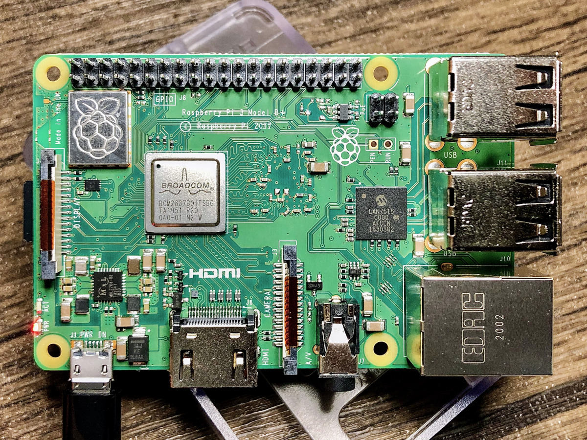
I have used an a third-generation Raspberry Pi 3 Model B+ single-board computer (SBC), to serve as an IoT Gateway. This Raspberry Pi model features a 1.4GHz Cortex-A53 (ARMv8) 64-bit quad-core processor System on a Chip (SoC), 1GB LPDDR2 SDRAM, dual-band wireless LAN, Bluetooth 4.2 BLE, and Gigabit Ethernet (Amazon: USD 42.99).
To follow along with the post, you could substitute the Raspberry Pi for any Linux-based machine to run the included sample Python script.
LoRa Transceiver Modules
To transmit the IoT sensor data between the IoT device, containing the embedded sensors, and the IoT gateway, I have used the REYAX RYLR896 LoRa transceiver module (Amazon: USD 19.50 x 2). The transceiver modules are commonly referred to as a universal asynchronous receiver-transmitter (UART). A UART is a computer hardware device for asynchronous serial communication in which the data format and transmission speeds are configurable.

According to the manufacturer, REYAX, the RYLR896 contains the Semtech SX1276 long-range, low power transceiver. The RYLR896 module provides ultra-long range spread spectrum communication and high interference immunity while minimizing current consumption. This transceiver operates at both the 868 and 915 MHz frequency ranges. We will be transmitting at 915 MHz for North America, in this post. Each RYLR896 module contains a small, PCB integrated, helical antenna.
Security
The RYLR896 is capable of the AES 128-bit data encryption. Using the Advanced Encryption Standard (AES), we will encrypt the data sent from the IoT device to the IoT gateway, using a 32 hex digit password (128 bits / 4 bits/hex digit = 32 hex digits). Using hexadecimal notation, the password is limited to digits 0–9 and characters A–F.
USB to TTL Serial Converter Adapter
Optionally, to configure, test, and debug the RYLR896 LoRa transceiver module directly from your laptop, you can use a USB to TTL serial converter adapter. I currently use the IZOKEE FT232RL FTDI USB to TTL Serial Converter Adapter Module for 3.3V and 5V (Amazon: USD 9.49 for 2). The 3.3V RYLR896 module easily connects to the USB to TTL Serial Converter Adapter using the TXD/TX, RXD/RX, VDD/VCC, and GND pins. We use serial communication to send and receive data through TX (transmit) and RX (receive) pins. The wiring is shown below: VDD to VCC, GND to GND, TXD to RX, and RXD to TX.

The FT232RL has support for baud rates up to 115,200 bps, which is the speed we will use to communicate with the RYLR896 module.
Arduino Sketch
For those not familiar with Arduino, a sketch is the name that Arduino uses for a program. It is the unit of code that is uploaded into non-volatile flash memory and runs on an Arduino board. The Arduino language is a set of C and C++ functions. All standard C and C++ constructs supported by the avr-g++ compiler should work in Arduino.
For this post, the sketch, lora_iot_demo.ino, contains all the code necessary to collect and securely transmit the environmental sensor data, including temperature, relative humidity, barometric pressure, RGB color, and ambient light intensity, using the LoRaWAN protocol. All code for this post, including the sketch, can be found on GitHub.
This file contains bidirectional Unicode text that may be interpreted or compiled differently than what appears below. To review, open the file in an editor that reveals hidden Unicode characters.
Learn more about bidirectional Unicode characters
| /* | |
| Description: Transmits Arduino Nano 33 BLE Sense sensor telemetry over LoRaWAN, | |
| including temperature, humidity, barometric pressure, and color, | |
| using REYAX RYLR896 transceiver modules | |
| http://reyax.com/wp-content/uploads/2020/01/Lora-AT-Command-RYLR40x_RYLR89x_EN.pdf | |
| Author: Gary Stafford | |
| */ | |
| #include <Arduino_HTS221.h> | |
| #include <Arduino_LPS22HB.h> | |
| #include <Arduino_APDS9960.h> | |
| const int UPDATE_FREQUENCY = 5000; // update frequency in ms | |
| const float CALIBRATION_FACTOR = -4.0; // temperature calibration factor (Celsius) | |
| const int ADDRESS = 116; | |
| const int NETWORK_ID = 6; | |
| const String PASSWORD = "92A0ECEC9000DA0DCF0CAAB0ABA2E0EF"; | |
| const String DELIMITER = "|"; | |
| void setup() | |
| { | |
| Serial.begin(9600); | |
| Serial1.begin(115200); // default baud rate of module is 115200 | |
| delay(1000); // wait for LoRa module to be ready | |
| // needs all need to be same for receiver and transmitter | |
| Serial1.print((String)"AT+ADDRESS=" + ADDRESS + "\r\n"); | |
| delay(200); | |
| Serial1.print((String)"AT+NETWORKID=" + NETWORK_ID + "\r\n"); | |
| delay(200); | |
| Serial1.print("AT+CPIN=" + PASSWORD + "\r\n"); | |
| delay(200); | |
| Serial1.print("AT+CPIN?\r\n"); // confirm password is set | |
| if (!HTS.begin()) | |
| { // initialize HTS221 sensor | |
| Serial.println("Failed to initialize humidity temperature sensor!"); | |
| while (1); | |
| } | |
| if (!BARO.begin()) | |
| { // initialize LPS22HB sensor | |
| Serial.println("Failed to initialize pressure sensor!"); | |
| while (1); | |
| } | |
| // avoid bad readings to start bug | |
| // https://forum.arduino.cc/index.php?topic=660360.0 | |
| BARO.readPressure(); | |
| delay(1000); | |
| if (!APDS.begin()) | |
| { // initialize APDS9960 sensor | |
| Serial.println("Failed to initialize color sensor!"); | |
| while (1); | |
| } | |
| } | |
| void loop() | |
| { | |
| updateReadings(); | |
| delay(UPDATE_FREQUENCY); | |
| } | |
| void updateReadings() | |
| { | |
| float temperature = getTemperature(CALIBRATION_FACTOR); | |
| float humidity = getHumidity(); | |
| float pressure = getPressure(); | |
| int colors[4]; | |
| getColor(colors); | |
| String payload = buildPayload(temperature, humidity, pressure, colors); | |
| // Serial.println("Payload: " + payload); // display the payload for debugging | |
| Serial1.print(payload); // send the payload over LoRaWAN WiFi | |
| displayResults(temperature, humidity, pressure, colors); // display the results for debugging | |
| } | |
| float getTemperature(float calibration) | |
| { | |
| return HTS.readTemperature() + calibration; | |
| } | |
| float getHumidity() | |
| { | |
| return HTS.readHumidity(); | |
| } | |
| float getPressure() | |
| { | |
| return BARO.readPressure(); | |
| } | |
| void getColor(int c[]) | |
| { | |
| // check if a color reading is available | |
| while (!APDS.colorAvailable()) | |
| { | |
| delay(5); | |
| } | |
| int r, g, b, a; | |
| APDS.readColor(r, g, b, a); | |
| c[0] = r; | |
| c[1] = g; | |
| c[2] = b; | |
| c[3] = a; | |
| } | |
| void displayResults(float t, float h, float p, int c[]) | |
| { | |
| Serial.print("Temperature: "); | |
| Serial.println(t); | |
| Serial.print("Humidity: "); | |
| Serial.println(h); | |
| Serial.print("Pressure: "); | |
| Serial.println(p); | |
| Serial.print("Color (r, g, b, a): "); | |
| Serial.print(c[0]); | |
| Serial.print(", "); | |
| Serial.print(c[1]); | |
| Serial.print(", "); | |
| Serial.print(c[2]); | |
| Serial.print(", "); | |
| Serial.println(c[3]); | |
| Serial.println("———-"); | |
| } | |
| String buildPayload(float t, float h, float p, int c[]) | |
| { | |
| String readings = ""; | |
| readings += t; | |
| readings += DELIMITER; | |
| readings += h; | |
| readings += DELIMITER; | |
| readings += p; | |
| readings += DELIMITER; | |
| readings += c[0]; | |
| readings += DELIMITER; | |
| readings += c[1]; | |
| readings += DELIMITER; | |
| readings += c[2]; | |
| readings += DELIMITER; | |
| readings += c[3]; | |
| String payload = ""; | |
| payload += "AT+SEND="; | |
| payload += ADDRESS; | |
| payload += ","; | |
| payload += readings.length(); | |
| payload += ","; | |
| payload += readings; | |
| payload += "\r\n"; | |
| return payload; | |
| } |
AT Commands
Communications with the RYLR896’s long-range modem is done using AT commands. AT commands are instructions used to control a modem. AT is the abbreviation of ATtention. Every command line starts with “AT”. That is why modem commands are called AT commands, according to Developer’s Home. A complete list of AT commands can be downloaded as a PDF from the RYLR896 product page.
To efficiently transmit the environmental sensor data from the IoT sensor to the IoT gateway, the sketch concatenates the sensor values together in a single string. The string will be incorporated into AT command to send the data to the RYLR896 LoRa transceiver module. To make it easier to parse the sensor data on the IoT gateway, we will delimit the sensor values with a pipe (|), as opposed to a comma. The maximum length of the payload (sensor data) is 240 bytes.
Below, we see an example of an AT command used to send the sensor data from the IoT sensor and the corresponding unencrypted data received by the IoT gateway. Both strings contain the LoRa transmitter Address ID, payload length, and the payload. The data received by the IoT gateway also contains the Received signal strength indicator (RSSI), and Signal-to-noise ratio (SNR).

Configure, Test, and Debug
As discussed earlier, to configure, test, and debug the RYLR896 LoRa transceiver modules without the use of the IoT gateway, you can use a USB to TTL serial converter adapter. The sketch is loaded on the Arduino Sense (the IoT device) and actively transmits data through one of the RYLR896 modules (shown below right). The other RYLR896 module is connected to your laptop’s USB port, via the USB to TTL serial converter adapter (shown below left). Using a terminal and the screen command, or the Arduino desktop application’s Serial Terminal, we can receive the sensor data from the Arduino Sense.

Using a terminal on your laptop, we first need to locate the correct virtual console (aka virtual terminal). On Linux or Mac, the virtual consoles are represented by device special files, such as /dev/tty1, /dev/tty2, and so forth. To find the virtual console for the USB to TTL serial converter adapter plugged into the laptop, use the following command.
ls -alh /dev/tty.*
We should see a virtual console with a name similar to /dev/tty.usbserial-.
... /dev/tty.Bluetooth-Incoming-Port
... /dev/tty.GarysBoseQC35II-SPPDev
... /dev/tty.a483e767cbac-Bluetooth-
... /dev/tty.usbserial-A50285BI
To connect to the RYLR896 module via the USB to TTL serial converter adapter, using the virtual terminal, we use the screen command and connect at a baud rate of 115,200 bps.
screen /dev/tty.usbserial-A50285BI 115200
If everything is configured and working correctly, we should see data being transmitted from the Arduino Sense and received by the local machine, at five second intervals. Each line of unencrypted data transmitted will look similar to the following, +RCV=116,25,22.18|41.57|99.74|2343|1190|543|4011,-34,47. In the example below, the AES 128-bit data encryption is not enabled on the Arduino, yet. With encryption turned on the sensor data (the payload) would appear garbled.

Even easier than the screen command, we can also use the Arduino desktop application’s Serial Terminal, as shown in the following short screen recording. Select the correct Port (virtual console) from the Tools menu and open the Serial Terminal. Since the transmitted data should be secured using AES 128-bit data encryption, we need to send an AT command (AT+CPIN) containing the transceiver module’s common password, to correctly decrypt the data on the receiving device (e.g., AT+CPIN=92A0ECEC9000DA0DCF0CAAB0ABA2E0EF).
Receiving Data on IoT Gateway
The Raspberry Pi will act as an IoT gateway, receiving the environmental sensor data from the IoT device, the Arduino. The Raspberry Pi will run a Python script, rasppi_lora_receiver.py, which will receive and decrypt the data payload, parse the sensor values, and display the values in the terminal. The script uses the pyserial, the Python Serial Port Extension. This Python module encapsulates the access for the serial port.
This file contains bidirectional Unicode text that may be interpreted or compiled differently than what appears below. To review, open the file in an editor that reveals hidden Unicode characters.
Learn more about bidirectional Unicode characters
| import logging | |
| import time | |
| from argparse import ArgumentParser | |
| from datetime import datetime | |
| import serial | |
| from colr import color as colr | |
| # LoRaWAN IoT Sensor Demo | |
| # Using REYAX RYLR896 transceiver modules | |
| # Author: Gary Stafford | |
| # Requirements: python3 -m pip install –user -r requirements.txt | |
| # To Run: python3 ./rasppi_lora_receiver.py –tty /dev/ttyAMA0 –baud-rate 115200 | |
| # constants | |
| ADDRESS = 116 | |
| NETWORK_ID = 6 | |
| PASSWORD = "92A0ECEC9000DA0DCF0CAAB0ABA2E0EF" | |
| def main(): | |
| logging.basicConfig(filename='output.log', filemode='w', level=logging.DEBUG) | |
| args = get_args() # get args | |
| payload = "" | |
| print("Connecting to REYAX RYLR896 transceiver module…") | |
| serial_conn = serial.Serial( | |
| port=args.tty, | |
| baudrate=int(args.baud_rate), | |
| timeout=5, | |
| parity=serial.PARITY_NONE, | |
| stopbits=serial.STOPBITS_ONE, | |
| bytesize=serial.EIGHTBITS | |
| ) | |
| if serial_conn.isOpen(): | |
| set_lora_config(serial_conn) | |
| check_lora_config(serial_conn) | |
| while True: | |
| serial_payload = serial_conn.readline() # read data from serial port | |
| if len(serial_payload) > 0: | |
| try: | |
| payload = serial_payload.decode(encoding="utf-8") | |
| except UnicodeDecodeError: # receiving corrupt data? | |
| logging.error("UnicodeDecodeError: {}".format(serial_payload)) | |
| payload = payload[:-2] | |
| try: | |
| data = parse_payload(payload) | |
| print("\n———-") | |
| print("Timestamp: {}".format(datetime.now())) | |
| print("Payload: {}".format(payload)) | |
| print("Sensor Data: {}".format(data)) | |
| display_temperature(data[0]) | |
| display_humidity(data[1]) | |
| display_pressure(data[2]) | |
| display_color(data[3], data[4], data[5], data[6]) | |
| except IndexError: | |
| logging.error("IndexError: {}".format(payload)) | |
| except ValueError: | |
| logging.error("ValueError: {}".format(payload)) | |
| # time.sleep(2) # transmission frequency set on IoT device | |
| def eight_bit_color(value): | |
| return int(round(value / (4097 / 255), 0)) | |
| def celsius_to_fahrenheit(value): | |
| return (value * 1.8) + 32 | |
| def display_color(r, g, b, a): | |
| print("12-bit Color values (r,g,b,a): {},{},{},{}".format(r, g, b, a)) | |
| r = eight_bit_color(r) | |
| g = eight_bit_color(g) | |
| b = eight_bit_color(b) | |
| a = eight_bit_color(a) # ambient light intensity | |
| print(" 8-bit Color values (r,g,b,a): {},{},{},{}".format(r, g, b, a)) | |
| print("RGB Color") | |
| print(colr("\t\t", fore=(127, 127, 127), back=(r, g, b))) | |
| print("Light Intensity") | |
| print(colr("\t\t", fore=(127, 127, 127), back=(a, a, a))) | |
| def display_pressure(value): | |
| print("Barometric Pressure: {} kPa".format(round(value, 2))) | |
| def display_humidity(value): | |
| print("Humidity: {}%".format(round(value, 2))) | |
| def display_temperature(value): | |
| temperature = celsius_to_fahrenheit(value) | |
| print("Temperature: {}°F".format(round(temperature, 2))) | |
| def get_args(): | |
| arg_parser = ArgumentParser(description="BLE IoT Sensor Demo") | |
| arg_parser.add_argument("–tty", required=True, help="serial tty", default="/dev/ttyAMA0") | |
| arg_parser.add_argument("–baud-rate", required=True, help="serial baud rate", default=1152000) | |
| args = arg_parser.parse_args() | |
| return args | |
| def parse_payload(payload): | |
| # input: +RCV=116,29,23.94|37.71|99.89|16|38|53|80,-61,56 | |
| # output: [23.94, 37.71, 99.89, 16.0, 38.0, 53.0, 80.0] | |
| payload = payload.split(",") | |
| payload = payload[2].split("|") | |
| payload = [float(i) for i in payload] | |
| return payload | |
| def set_lora_config(serial_conn): | |
| # configures the REYAX RYLR896 transceiver module | |
| serial_conn.write(str.encode("AT+ADDRESS=" + str(ADDRESS) + "\r\n")) | |
| serial_payload = (serial_conn.readline())[:-2] | |
| print("Address set?", serial_payload.decode(encoding="utf-8")) | |
| serial_conn.write(str.encode("AT+NETWORKID=" + str(NETWORK_ID) + "\r\n")) | |
| serial_payload = (serial_conn.readline())[:-2] | |
| print("Network Id set?", serial_payload.decode(encoding="utf-8")) | |
| serial_conn.write(str.encode("AT+CPIN=" + PASSWORD + "\r\n")) | |
| time.sleep(1) | |
| serial_payload = (serial_conn.readline())[:-2] | |
| print("AES-128 password set?", serial_payload.decode(encoding="utf-8")) | |
| def check_lora_config(serial_conn): | |
| serial_conn.write(str.encode("AT?\r\n")) | |
| serial_payload = (serial_conn.readline())[:-2] | |
| print("Module responding?", serial_payload.decode(encoding="utf-8")) | |
| serial_conn.write(str.encode("AT+ADDRESS?\r\n")) | |
| serial_payload = (serial_conn.readline())[:-2] | |
| print("Address:", serial_payload.decode(encoding="utf-8")) | |
| serial_conn.write(str.encode("AT+NETWORKID?\r\n")) | |
| serial_payload = (serial_conn.readline())[:-2] | |
| print("Network id:", serial_payload.decode(encoding="utf-8")) | |
| serial_conn.write(str.encode("AT+IPR?\r\n")) | |
| serial_payload = (serial_conn.readline())[:-2] | |
| print("UART baud rate:", serial_payload.decode(encoding="utf-8")) | |
| serial_conn.write(str.encode("AT+BAND?\r\n")) | |
| serial_payload = (serial_conn.readline())[:-2] | |
| print("RF frequency", serial_payload.decode(encoding="utf-8")) | |
| serial_conn.write(str.encode("AT+CRFOP?\r\n")) | |
| serial_payload = (serial_conn.readline())[:-2] | |
| print("RF output power", serial_payload.decode(encoding="utf-8")) | |
| serial_conn.write(str.encode("AT+MODE?\r\n")) | |
| serial_payload = (serial_conn.readline())[:-2] | |
| print("Work mode", serial_payload.decode(encoding="utf-8")) | |
| serial_conn.write(str.encode("AT+PARAMETER?\r\n")) | |
| serial_payload = (serial_conn.readline())[:-2] | |
| print("RF parameters", serial_payload.decode(encoding="utf-8")) | |
| serial_conn.write(str.encode("AT+CPIN?\r\n")) | |
| serial_payload = (serial_conn.readline())[:-2] | |
| print("AES128 password of the network", | |
| serial_payload.decode(encoding="utf-8")) | |
| if __name__ == "__main__": | |
| main() |
Prior to running the Python script, we can test and debug the connection from the Arduino Sense to the Raspberry Pi using a general application such as Minicom. Minicom is a text-based modem control and terminal emulator program. To install Minicom on the Raspberry Pi, use the following command.
sudo apt-get install minicom
To run Minicom or the Python script, we will need to know the virtual console of the serial connection (Serial1 in the script) used to communicate with the RYLR896 module, wired to the Raspberry Pi. This can found using the following command.
dmesg | grep -E --color 'serial|tty'
Search for a line, similar to the last line, shown below. Note the name of the virtual console, in my case, ttyAMA0.
[    0.000000] Kernel command line: coherent_pool=1M bcm2708_fb.fbwidth=656 bcm2708_fb.fbheight=416 bcm2708_fb.fbswap=1 vc_mem.mem_base=0x1ec00000 vc_mem.mem_size=0x20000000  dwc_otg.lpm_enable=0 console=tty1 root=PARTUUID=509d1565-02 rootfstype=ext4 elevator=deadline fsck.repair=yes rootwait quiet splash plymouth.ignore-serial-consoles
[    0.000637] console [tty1] enabled
[    0.863147] uart-pl011 20201000.serial: cts_event_workaround enabled
[    0.863289] 20201000.serial: ttyAMA0 at MMIO 0x20201000 (irq = 81, base_baud = 0) is a PL011 rev2
To view the data received from the Arduino Sense, using Minicom, use the following command, substituting the virtual console value, found above.
minicom -b 115200 -o -D /dev/ttyAMA0
If successful, we should see output similar to the lower right terminal window. Data is being transmitted by the Arduino Sense and being received by the Raspberry Pi, via LoRaWAN. In the below example, the AES 128-bit data encryption is not enabled on the Arduino, yet. With encryption turned on the sensor data (the payload) would appear garbled.

IoT Gateway Python Script
To run the Python script on the Raspberry Pi, use the following command, substituting the name of the virtual console (e.g., /dev/ttyAMA0).
python3 ./rasppi_lora_receiver.py \
  --tty /dev/ttyAMA0 --baud-rate 115200
The script starts by configuring the RYLR896 and outputting that configuration to the terminal. If successful, we should see the following informational output.
Connecting to REYAX RYLR896 transceiver module...

Address set? +OK
Network Id set? +OK
AES-128 password set? +OK
Module responding? +OK

Address: +ADDRESS=116
Firmware version: +VER=RYLR89C_V1.2.7
Network Id: +NETWORKID=6
UART baud rate: +IPR=115200
RF frequency +BAND=915000000
RF output power +CRFOP=15
Work mode +MODE=0
RF parameters +PARAMETER=12,7,1,4
AES-128 password of the network +CPIN=92A0ECEC9000DA0DCF0CAAB0ABA2E0EF
Once configured, the script will receive the data from the Arduino Sense, decrypt the data, parse the sensor values, and format and display the values within the terminal.
The following screen recording shows a parallel view of both the Arduino Serial Monitor (upper right window) and the Raspberry Pi’s terminal output (lower right window). The Raspberry Pi (receiver) receives data from the Arduino (transmitter). The Raspberry Pi successfully reads, decrypts, interprets, and displays the sensor data, including displaying color swatches for the RGB and light intensity sensor readings.
Conclusion
In this post, we explored the use of the LoRa and LoRaWAN protocols to transmit environmental sensor data from an IoT device to an IoT gateway. Given its low energy consumption, long-distance transmission capabilities, and well-developed protocols, LoRaWAN is an ideal long-range wireless protocol for IoT devices.
This blog represents my own viewpoints and not of my employer, Amazon Web Services (AWS). All product names, logos, and brands are the property of their respective owners.
Prevent Motion From Running Without a Camera Connected
Posted by Gary A. Stafford in Bash Scripting, Raspberry Pi, Software Development on July 19, 2013
Introduction
If you read my post, Raspberry Pi-Powered Dashboard Video Camera Using Motion and FFmpeg, you know Motion with FFmpeg on a Raspberry Pi makes an ideal dashboard camera system. However, an issue I still struggled with when using the dash-cam was Motion running without a webcam connected.
When I start my car, the Raspberry Pi boots-up, and subsequently, Motion starts. No interaction with the Pi is required. The dash-cam starts capturing images and making the time-lapse video. However, when I get home and plug my Pi back into my local network, Motion starts up again and starts recording blank images and creating the time-lapse video, even though there is no webcam connected.
To get prevent Motion from starting up without a webcam connected, I’ve added a simple function to the Motion startup script. When the system calls Motion on startup, the new function checks if a webcam is connected. If not, it immediately exits the script, without ever starting Motion. No blank images or empty time-lapse videos are created. This saves a lot of wasted processing on the Pi. It also saves a lot of wasted time moving videos and images off the Pi that end up being blank, because no webcam was connected.
Find Your Webcam
First, attach your webcam to the Raspberry Pi. Run the following command to list the USB devices connected to the Pi:
lsusb
You should see similar output to the example below. Note your webcam’s ID(s). I ran the command twice in this example, to identify both of my webcams.

Identifying Webcams with lsusb Command
There are several ways to detect your webcam, depending on you Linux distro. I found this post particularly helpful, The Webcam HOWTO.
Modify Motion
Next, open the Motion startup script, using the following command:
sudo nano /etc/init.d/motion
Add the following ‘check_for_webcam ()’ function to the top of the script, adjacent to the existing ‘check_daemon_enabled()’ function:
# Check if specific webcam(s) are connected to Pi
check_for_webcam () {
    if lsusb | grep -s -q -e 0000:ABCD
    then
        echo "Webcam found. Continuing..."
        return 0
    else
        echo "No webcam found? Shutting down Motion!"
        return 1
    fi
}
You will need to modify the function, changing the string ‘0000:ABCD’, to match your webcam’s ID. If you change your webcam model, remember to update the ID you entered in this function.
Next add the following statement to the beginning of the ‘start’ function. This code calls the new function when Motion’s ‘start’ command is executed. If no webcam is found, the Motion script exits without starting.
if ! check_for_webcam; then
    exit 1
fi
In my example below, I have two possible webcams that might be connected, so I search (grep) for either ID.

Modifying Motion Startup Script
Testing the Script Change
Save and close the Motion script. To test the script is working, run the following command to stop Motion:
sudo /etc/init.d/motion stop
Unplug your webcam from the Raspberry Pi. Then, run the following command to start Motion:
sudo /etc/init.d/motion start
You should see the following output:
No webcam found? Shutting down Motion!
Now, plug your webcam back in and run the ‘start’ command, again. You should now see the following output:
Webcam found. Continuing...

Starting Motion With and Without Webcam
Conclusion
Now, when you start the Raspberry Pi and don’t have a web-cam connected, Motion will no longer automatically start. Just remember, if you don’t have a way to interact directly with your Pi, you will need to restart the Pi to get Motion running again after connecting a webcam.
Travel-Size Wireless Router for Your Raspberry Pi
Posted by Gary A. Stafford in Bash Scripting, Raspberry Pi, Software Development on July 15, 2013
Introduction
Recently, I purchased a USB-powered wireless router for to use with my Raspberry Pi when travelling. In an earlier post, Raspberry Pi-Powered Dashboard Video Camera Using Motion and FFmpeg, I discussed the use of the Raspberry Pi, combined with a webcam, Motion, and FFmpeg, to create a low-cost dashboard video camera. Like many, I find one the big challenges with the Raspberry Pi, is how to connect and interact with it. Being in my car, and usually out of range of my home’s wireless network, except maybe in the garage, this becomes even more of an issue. That’s where adding an inexpensive travel-size router to my vehicle comes in handy.
I chose the TP-LINK TL-WR702N Wireless N150 Travel Router, sold by Amazon. The TP-LINK router, described as ‘nano size’, measures only 2.2 inches square by 0.7 inches wide. It has several modes of operation, including as a router, access point, client, bridge, or repeater. It operates at wireless speeds up to 150Mpbs and is compatible with IEEE 802.11b/g/n networks. It supports several common network security protocols, including WEP, WPA/WPA2, WPA-PSK/WPA2-PSK encryption. For $22 USD, what more could you ask for!

My goal with the router was to do the following:
- Have the Raspberry Pi auto-connect to the new TP-LINK router’s wireless network when in range, just like my home network.
- Since I might still be in range of my home network, have the Raspberry Pi try to connect to the TP-LINK first, before falling back to my home network.
- Ensure the network was relatively secure, since I would be exposed to many more potential threats when traveling.
My vehicle has two power outlets. I plug my Raspberry Pi into one outlet and the router into the other. You could daisy chain the router off the Pi. However, my Pi’s ports are in use my the USB wireless adapter and the USB webcam. Using the TP-LINK router, I can easily connect to the Raspberry Pi with my mobile phone or tablet, using an SSH client.

Using Fing to Locate the Pi on the TP-LINK Wireless Network
When I arrive at my destination, I log into the Pi and do a proper shutdown. This activates my shutdown script (see my last post), which moves the newly created Motion/FFmpeg time-lapse dash-cam videos to a secure folder on my Pi, before powering down.

Using SSH Terminal for iOS to Shutdown the Pi
Of course there are many other uses for the router. For example, I can remove the Pi and router from my car and plug it back in at the hotel while traveling, or power the router from my laptop while at work or the coffee shop. I now have my own private wireless network wherever I am to use the Raspberry Pi, or work with other users. Remember the TP-LINK can act as a router, access point, client, bridge, or a repeater.

The Raspberry Pi and Router both fit in a Small Container for Travel
Network Security
Before configuring your Raspberry Pi, the first thing you should do is change all the default security related settings for the router. Start with the default SSID and the PSK password. Both these default values are printed right on the router. That’s motivation enough to change!

Additionally, change the default IP address of the router and the username and password for the browser-based Administration Console.

Lastly, pick the most secure protocol possible. I chose ‘WPA-PSK/WPA2-PSK’. All these changes are done through the TP-LINK’s browser-based Administration Console.
Configuring Multiple Wireless Networks
In an earlier post, Installing a Miniature WiFi Module on the Raspberry Pi (w/ Roaming Enabled), I detailed the installation and configuration of a Miniature WiFi Module, from Adafruit Industries, on a Pi running Soft-float Debian “wheezy”. I normally connect my Pi to my home wireless network. I wanted to continue to do this in the house, but connect the new router when traveling.
Based on the earlier post, I was already using Jouni Malinen’s wpa_supplicant, the WPA Supplicant for Linux, BSD, Mac OS X, and Windows with support for WPA and WPA2. This made network configuration relatively simple. If you use wpa_supplicant, your ‘/etc/network/interfaces’ file should look like the following. If you’re not familiar with configuring the interfaces file for wpa_supplicant, this post on NoWiresSecurity.com is a good starting point.
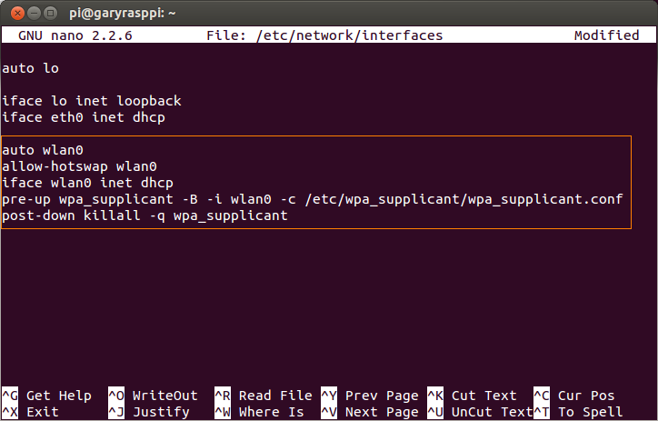
Note that in this example, I am using DHCP for all wireless network connections. If you chose to use static IP addresses for any of the networks, you will have to change the interfaces file accordingly. Once you add multiple networks, configuring static IP addresses for each network, becomes more complex. That is my next project…
First, I generated a new pre-shared key (PSK) for the router’s SSID configuration using the following command. Substitute your own SSID (‘your_ssid’) and passphrase (‘your_passphrase’).
wpa_passphrase your_ssid your_passphrase
Based your SSID and passphrase, this command will generate a pre-shared key (PSK), similar to the following. Save or copy the PSK to the clipboard. We will need the PSK in the next step.

Then, I modified my wpa_supplicant configuration file with the following command:
sudo nano /etc/wpa_supplicant/wpa_supplicant.conf
I added the second network configuration, similar to the existing configuration for my home wireless network, using the newly generated PSK. Below is an example of what mine looks like (of course, not the actual PSKs).

Depending on your Raspberry Pi and router configurations, your wpa_supplicant configuration will look slightly different. You may wish to add more settings. Don’t consider my example the absolute right way for your networks.
Wireless Network Priority
Note the priority of the TP-LINK router is set to 2, while my home NETGEAR router is set to 1. This ensures wpa_supplicant will attempt to connect to the TP-LINK network first, before attempting the home network. The higher number gets priority. The best resource I’ve found, which explains all the configuration options is detail, is here. In this example wpa_supplicant configuration file, priority is explained this way, ‘by default, all networks will get same priority group (0). If some of the networks are more desirable, this field can be used to change the order in which wpa_supplicant goes through the networks when selecting a BSS. The priority groups will be iterated in decreasing priority (i.e., the larger the priority value, the sooner the network is matched against the scan results). Within each priority group, networks will be selected based on security policy, signal strength, etc.’
Conclusion
If you want an easy, inexpensive, secure way to connect to your Raspberry Pi, in the vehicle or other location, a travel-size wireless router is a great solution. Best of all, configuring it for your Raspberry Pi is simple if you use wpa_supplicant.
Raspberry Pi-Powered Dashboard Video Camera Using Motion and FFmpeg
Posted by Gary A. Stafford in Bash Scripting, Raspberry Pi, Software Development on June 30, 2013
Demonstrate the use of the Raspberry Pi and a basic webcam, along with Motion and FFmpeg, to build low-cost dashboard video camera for your daily commute.

Dashboard Video Cameras
Most of us remember the proliferation of dashboard camera videos of the February 2013 meteor racing across the skies of Russia. This rare astronomical event was captured on many Russian motorist’s dashboard cameras. Due to the dangerous driving conditions in Russia, many drivers rely on dashboard cameras for insurance and legal purposes. In the United States, we are more use to seeing dashboard cameras used by law-enforcement. Who hasn’t seen those thrilling police videos of car crashes, drunk drivers, and traffic stops gone wrong.
Although driving in the United States is not as dangerous as in Russia, there is reason we can’t also use dashboard cameras. In case you are involved in an accident, you will have a video record of the event for your insurance company. If you witness an accident or other dangerous situation, your video may help law enforcement and other emergency responders. Maybe you just want to record a video diary of your next road trip.
A wide variety of dashboard video cameras, available for civilian vehicles, can be seen on Amazon’s website. They range in price and quality from less that $50 USD to well over $300 USD or more, depending on their features. In a popular earlier post, Remote Motion-Activated Web-Based Surveillance with Raspberry Pi, I demonstrated the use of the Raspberry Pi and a webcam, along with Motion and FFmpeg, to provide low-cost web-based, remote surveillance. There are many other uses for this combination of hardware and software, including as a dashboard video camera.
Methods for Creating Dashboard Camera Videos
I’ve found two methods for capturing dashboard camera videos. The first and easiest method involves configuring Motion to use FFmpeg to create a video. FFmpeg creates a video from individual images (frames) taken at regular intervals while driving. The upside of the FFmpeg option, it gives you a quick ready-made video. The downside of FFmpeg option, your inability to fully control the high-level of video compression and high frame-rate (fps). This makes it hard to discern fine details when viewing the video.
Alternately, you can capture individual JPEG images and combine them using FFmpeg from the command line or using third-party movie-editing tools. The advantage of combining the images yourself, you have more control over the quality and frame-rate of the video. Altering the frame-rate, alters your perception of the speed of the vehicle recording the video. The only disadvantage of combining the images yourself, you have the extra steps involved to process the images into a video.
At one frame every two seconds (.5 fps), a 30 minute commute to work will generate 30 frames/minute x 30 minutes, or 900 jpeg images. At 640 x 480 pixels, depending on your jpeg compression ratio, that’s a lot of data to move around and crunch into a video. If you just want a basic record of your travels, use FFmpeg. If you want a higher-quality record of trip, maybe for a video-diary, combining the frames yourself is a better way to go.
Configuring Motion for a Dashboard Camera
The installation and setup of FFmpeg and Motion are covered in my earlier post so I won’t repeat that here. Below are several Motion settings I recommend starting with for use with a dashboard video camera. To configure Motion, open it’s configuration file, by entering the following command on your Raspberry Pi:
sudo nano /etc/motion/motion.conf
To use FFmpeg, the first method, find the ‘FFMPEG related options’ section of the configuration and locate ‘Use ffmpeg to encode a timelapse movie’. Enter a number for the ‘ffmpeg_timelapse’ setting. This is the rate at which images are captured and combined into a video. I suggest starting with 2 seconds. With a dashboard camera, you are trying to record important events as you drive. In as little as 2-3 seconds at 55 mph, you can miss a lot of action. Moving the setting down to 1 second will give more detail, but you will chew up a lot of disk space, if that is an issue for you. I would experiment with different values:
# Use ffmpeg to encode a timelapse movie
# Default value 0 = off - else save frame every Nth second
ffmpeg_timelapse 2
To use the ‘do-it-yourself’ FFmpeg method, locate the ‘Snapshots’ section. Find ‘Make automated snapshot every N seconds (default: 0 = disabled)’. Change the ‘snapshot_interval’ setting, using the same logic as the ‘ffmpeg_timelapse’ setting, above:
# Make automated snapshot every N seconds (default: 0 = disabled)
snapshot_interval 2
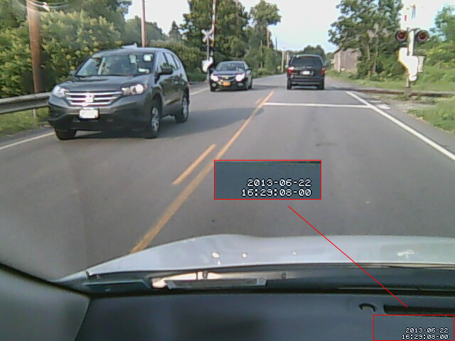
Irregardless of which method you choose (or use them both), you will want to tweak some more settings. In the ‘Text Display’ section, locate ‘Set to ‘preview’ will only draw a box in preview_shot pictures.’ Change the ‘locate’ setting to ‘off’. As shown in the video frame below, since you are moving in your vehicle most of the time, there is no sense turning on this option. Motion cannot differentiate between the highway zipping by the camera and the approaching vehicles. Everything is in motion to the camera, the box just gets in the way:
# Set to 'preview' will only draw a box in preview_shot pictures.
locate off

Optionally, I recommend turning on the time-stamp option. This is found right below the ‘locate’ setting. Especially in the event of an accident, you want an accurate time-stamp on the video or still images (make sure you Raspberry Pi’s time is correct):
# Draws the timestamp using same options as C function strftime(3)
# Default: %Y-%m-%d\n%T = date in ISO format and time in 24 hour clock
# Text is placed in lower right corner
text_right %Y-%m-%d\n%T-%q
Starting with the largest, best quality images will ensure the video quality is optimal. Start with a large size capture and reduce it only if you are having trouble capturing the video quickly enough. These settings are found in the ‘Capture device options’ section:
# Image width (pixels). Valid range: Camera dependent, default: 352
width 640

# Image height (pixels). Valid range: Camera dependent, default: 288
height 480
Similarly, I suggest starting with a low amount of jpeg compression to maximize quality and only lower if necessary. This setting is found in the ‘Image File Output’ section:
# The quality (in percent) to be used by the jpeg compression (default: 75)
quality 90
Once you have completed the configuration of Motion, restart Motion for the changes to take effect:
sudo /etc/init.d/motion restart
Since you will be powering on your Raspberry Pi in your vehicle, and may have no way to reach Motion from a command line, you will want Motion to start capturing video and images for you automatically at startup. To enable Motion (the motion daemon) on start-up, edit the /etc/default/motion file.
sudo nano /etc/default/motion
Change the ‘start_motion_daemon‘ setting to ‘yes’. If you decide to stop using the Raspberry Pi for capturing video, remember to disable this option. Motion will keep generating video and images, even without a camera connected, if the daemon process is running.
Capturing Dashboard Video
Although taking dashboard camera videos with your Raspberry Pi sounds easy, it presents several challenges. How will you mount your camera? How will you adjust your camera’s view? How will you power your Raspberry Pi in the vehicle? How will you power-down your Raspberry Pi from the vehicle? How will you make sure Motion is running? How will you get the video and images off the Raspberry Pi? Do you have one a mini keyboard and LCD monitor to use in your vehicle? Or, is your Raspberry Pi on your wireless network? If so, do you know how to bring up the camera’s view and Motion’s admin site on your smartphone’s web-browser?
My start-up process is as follows:
- Start my car.
- Plug the webcam and the power cable into the Raspberry Pi.
- Let the Raspberry Pi boot up fully and allow Motion to start. This takes less than one minute.
- Open the http address Motion serves up using my mobile browser.
(Since my Raspberry Pi has a wireless USB adapter installed and I’m still able to connect from my garage). - Adjust the camera using the mobile browser view from the camera.
- Optionally, use Motion’s ‘HTTP Based Control’ feature to adjust any Motion configurations, on-the-fly (great option).

Logitech Webcam C210 Webcam Mounted on Car Sun Visor

Raspberry Pi in Vehicle with iPhone Preview of Dashboard Camera

Adjusting Camera using iPhone WiFi Connection to Raspberry Pi

Using Motion’s HTTP Based Control on iPhone Mobile Web Browser
Once I reach my destination, I copy the video and/or still image frames off the Raspberry Pi:
- Let the car run for at least 1-2 minutes after you stop. The Raspberry Pi is still processing the images and video.
- Copy the files off the Raspberry Pi over the local network, right from car (if in range of my LAN).
- Alternately, shut down the Raspberry Pi by using a SSH mobile app on your smartphone, or just shut the car off (this not the safest method!).
- Place the Pi’s SDHC card into my laptop and copy the video and/or still image frames.

Shutting Down Raspberry Pi Using SSH Terminal iPhone App
Here are some tips I’ve found to make creating dashboard camera video’s easier and better quality:
- Leave your camera in your vehicle once you mount and position it.
- Make sure your camera is secure so the vehicle’s vibrations while driving don’t create bouncy-images or change the position of the camera field of view.
- Clean your vehicle’s front window, inside and out. Bugs or other dirt are picked up by the camera and may affect the webcam’s focus.
- Likewise, film on the window from smoking or dirt will soften the details of the video and create harsh glare when driving on sunny days.
- Similarly, make sure your camera’s lens is clean.
- Keep your dashboard clear of objects such as paper, as it reflects on the window and will obscure the dashboard camera’s video.
- Constantly stopping your Raspberry Pi by shutting the vehicle off can potential damage the Raspberry Pi and/or corrupt the operating system.
- Make sure to keep your Raspberry Pi out of sight of potential thieves and the direct sun when you are not driving.
- Backup your Raspberry Pi’s SDHC card before using for dashboard camera, see Duplicating Your Raspberry Pi’s SDHC Card.
Creating Video from Individual Dashboard Camera Images
FFmpeg
If you choose the second method for capturing dashboard camera videos, the easiest way to combine the individual dashboard camera images is by calling FFmpeg from the command line. To create the example #3 video, shown below, I ran two commands from a Linux Terminal prompt. The first command is a bash command to rename all the images to four-digit incremented numbers (‘0001.jpg’, ‘0002.jpg’, ‘0003.jpg’, etc.). This makes it easier to execute the second command. I found this script on stackoverflow. It requires Gawk (‘sudo apt-get install gawk’). If you are unsure about running this command, make a copy of the original images in case something goes wrong.
The second command is a basic FFmpeg command to combine the images into a 20 fps MPEG-4 video file. More information on running FFmpeg can be found on their website. There is a huge number of options available with FFmpeg from the command line. Running this command, FFmpeg processed 4,666 frames at 640 x 480 pixels in 233.30 seconds, outputting a 147.5 Mb MPEG-4 video file.
find -name '*.jpg' | sort | gawk '{ printf "mv %s %04d.jpg\n", $0, NR }' | bash
ffmpeg -r 20 -qscale 2  -i %04d.jpg output.mp4

FFmpeg Command Line Video Creation Output
Example #3 – FFmpeg Video from Command Line
If you want to compress the video, you can chain a second FFmpeg command to the first one, similar to the one below. In my tests, this reduced the video size to 20-25% of the original uncompressed version.
ffmpeg -r 20 -qscale 2 -i %04d.jpg output.mp4 && ffmpeg -i output.mp4 -vcodec mpeg2video output_compressed.mp4
If your images are to dark (early morning or overcast) or have a color-cast (poor webcam or tinted-windows), you can use programs like ImageMagick to adjust all the images as a single batch. In example #5 below, I pre-processed all the images prior to making the video. With one ImageMagick command, I adjusting their levels to make them lighter and less flat.
mogrify -level 12%,98%,1.79 *.jpg
Example #5 – FFmpeg Uncompressed Video from Command Line
Windows MovieMaker
Using Windows MovieMaker was not my first choice, but I’ve had a tough time finding an equivalent Linux gui-based application. If you are going to create your own video from the still images, you need to be able to import and adjust thousands of images quickly and easily. I can import, create, and export a typical video of a 30 minute trip in 10 minutes with MovieMaker. With MovieMaker, you can also add titles, special effects, and so forth.

Single Images Combined in Windows MovieMaker
Sample Videos
Below are a few dashboard video examples using a variety of methods. In the first two examples, I captured still images and created the FFmpeg video at the same time. You can compare quality of Method #1 to #2.
Example #2a – Motion/FFmpeg Video
Example #2b – Windows MovieMaker
Example #5 – FFmpeg Compressed Video from Command Line
Example #6 – FFmpeg Compressed Video from Command Line
Useful Links
Renaming files in a folder to sequential numbers
ImageMagick: Command-line Options
ImageMagick: Mogrify — in-place batch processing
Duplicating Your Raspberry Pi’s SDHC Card
Posted by Gary A. Stafford in Software Development on February 12, 2013
There are a few reasons you might want to duplicate (clone/copy) your Raspberry Pi’s Secure Digital High-Capacity (SDHC) card. I had two, backup and a second Raspberry Pi. I spent untold hours installing and configuring software on your Raspberry Pi with Java, OpenCV, Motion, etc. Having a backup of all my work seemed like a good idea.
Second reason, a second Raspberry Pi. I wanted to set up a second Raspberry Pi, but didn’t want to spend the time to duplicate my previous efforts. Nor, could I probably ever duplicate the first Pi’s configuration, exactly. To ensure consistency across multiple Raspberry Pi’s, duplicating my first Raspberry Pi’s SDHC card made a lot of sense.
I found several posts on the web about duplicating an SDHC card. One of the best articles was on the PIXHAWK website. It only took me a few simple steps to backup my original 8 GB SDHC card, and then create a clone by copying the backup to a new 8 GB SDHC card, as follows:
1) Remove the original SDHC card from Raspberry Pi and insert it into a card reader on your computer. I strongly suggest locking the card to protect it against any mistakes while backing up.
2) Locate where the SDHC card is mounted on your computer. This can be done using GParted, or in a terminal window, using the ‘blkid’ (block device attributes) command. My Raspberry Pi’s SDHC card, with its three separate partitions was found at ‘/dev/sdb’.

GParted View of SDHC Card

Terminal Window View of Partitions
3) Use the ‘dd’ (convert and copy a file) command to duplicate the contents of the SDHC card to your computer. This can take a while and there is no progress bar. The command I used to back up the card to my computer’s $HOME directory was:
sudo dd if=/dev/sdb of=~/sdhc-card-bu.bin
4) Unmount and unlock the original SDHC card. Mount the new SDHC card. It should mount in the same place.
5) Reverse the process by copying the backup file, ‘sdhc-card-bu.bin’, to the new SDHC card. Again, this can take a while and there is no progress bar. The command I used was:
sudo dd if=~/sdhc-card-bu.bin of=/dev/sdb
Using ‘dd’, backups and restores the entire SDHC card, partitions and all. I was able to insert the card into a brand new Raspberry Pi and boot it up, without any problems.
Obviously, there are some things you may want to change on a cloned Raspberry Pi. For example, you should change the cloned Raspberry Pi’s host name, so it doesn’t conflict with the original Raspberry Pi on the network. This is easily done:
sudo nano /etc/hostname
sudo /etc/init.d/hostname.sh start
Also, changing the cloned Raspberry Pi’s root password is a wise idea for both security and sanity, especially if you have more than one Pi on your network. This guarantees you know which one you are logging into. This is easily done using the ‘passwd’ command:

Changing the Root Password on Raspberry Pi
Object Tracking on the Raspberry Pi with C++, OpenCV, and cvBlob
Posted by Gary A. Stafford in Bash Scripting, C++ Development, Raspberry Pi on February 9, 2013
Use C++ with OpenCV and cvBlob to perform image processing and object tracking on the Raspberry Pi, using a webcam.
Source code and compiled samples are now available on GitHub. The below post describes the original code on the ‘Master’ branch. As of May 2014, there is a revised and improved version of the project on the ‘rev05_2014’ branch, on GitHub. The README.md details the changes and also describes how to install OpenCV, cvBlob, and all dependencies!
Introduction
As part of a project with a local FIRST Robotics Competition (FRC) Team, I’ve been involved in developing a Computer Vision application for use on the Raspberry Pi. Our FRC team’s goal is to develop an object tracking and target acquisition application that could be run on the Raspberry Pi, as opposed to the robot’s primary embedded processor, a National Instrument’s NI cRIO-FRC II. We chose to work in C++ for its speed, We also decided to test two popular open-source Computer Vision (CV) libraries, OpenCV and cvBlob.
Due to its single ARM1176JZF-S 700 MHz ARM processor, a significant limitation of the Raspberry Pi is the ability to perform complex operations in real-time, such as image processing. In an earlier post, I discussed Motion to detect motion with a webcam on the Raspberry Pi. Although the Raspberry Pi was capable of running Motion, it required a greatly reduced capture size and frame-rate. And even then, the Raspberry Pi’s ability to process the webcam’s feed was very slow. I had doubts it would be able to meet the processor-intense requirements of this project.
Development for the Raspberry Pi
Using C++ in NetBeans 7.2.1 on Ubuntu 12.04.1 LTS and 12.10, I wrote several small pieces of code to demonstrate the Raspberry Pi’s ability to perform basic image processing and object tracking. Parts of the follow code are based on several OpenCV and cvBlob code examples, found in my research. Many of those examples are linked on the end of this article. Examples of cvBlob are especially hard to find.
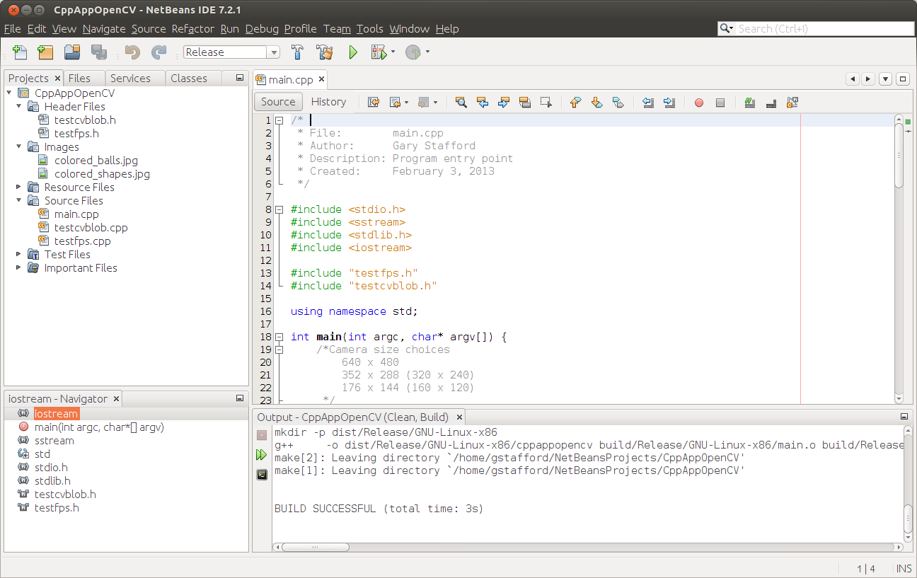
Project in NetBeans
The Code
There are five files: ‘main.cpp’, ‘testfps.cpp (testfps.h)’, and ‘testcvblob.cpp (testcvblob.h)’. The main.cpp file’s main method calls the test methods in the other two files. The cvBlob library only works with the pre-OpenCV 2.0. Therefore, I wrote all the code using the older objects and methods. The code is not written using the latest OpenCV 2.0 conventions. For example, cvBlob uses 1.0’s ‘IplImage’ image type instead 2.0’s newer ‘CvMat’ image type. My next projects is to re-write the cvBlob code to use OpenCV 2.0 conventions and/or find a newer library. The cvBlob library offered so many advantages, I felt not using the newer OpenCV 2.0 features was still worthwhile.
Main Program Method (main.cpp)
| /* | |
| * File: main.cpp | |
| * Author: Gary Stafford | |
| * Description: Program entry point | |
| * Created: February 3, 2013 | |
| */ | |
| #include <stdio.h> | |
| #include <sstream> | |
| #include <stdlib.h> | |
| #include <iostream> | |
| #include "testfps.hpp" | |
| #include "testcvblob.hpp" | |
| using namespace std; | |
| int main(int argc, char* argv[]) { | |
| int captureMethod = 0; | |
| int captureWidth = 0; | |
| int captureHeight = 0; | |
| if (argc == 4) { // user input parameters with call | |
| captureMethod = strtol(argv[1], NULL, 0); | |
| captureWidth = strtol(argv[2], NULL, 0); | |
| captureHeight = strtol(argv[3], NULL, 0); | |
| } else { // user did not input parameters with call | |
| cout << endl << "Demonstrations/Tests: " << endl; | |
| cout << endl << "(1) Test OpenCV - Show Webcam" << endl; | |
| cout << endl << "(2) Test OpenCV - No Webcam" << endl; | |
| cout << endl << "(3) Test cvBlob - Show Image" << endl; | |
| cout << endl << "(4) Test cvBlob - No Image" << endl; | |
| cout << endl << "(5) Test Blob Tracking - Show Webcam" << endl; | |
| cout << endl << "(6) Test Blob Tracking - No Webcam" << endl; | |
| cout << endl << "Input test # (1-6): "; | |
| cin >> captureMethod; | |
| // test 3 and 4 don't require width and height parameters | |
| if (captureMethod != 3 && captureMethod != 4) { | |
| cout << endl << "Input capture width (pixels): "; | |
| cin >> captureWidth; | |
| cout << endl << "Input capture height (pixels): "; | |
| cin >> captureHeight; | |
| cout << endl; | |
| if (!captureWidth > 0) { | |
| cout << endl << "Width value incorrect" << endl; | |
| return -1; | |
| } | |
| if (!captureHeight > 0) { | |
| cout << endl << "Height value incorrect" << endl; | |
| return -1; | |
| } | |
| } | |
| } | |
| switch (captureMethod) { | |
| case 1: | |
| TestFpsShowVideo(captureWidth, captureHeight); | |
| case 2: | |
| TestFpsNoVideo(captureWidth, captureHeight); | |
| break; | |
| case 3: | |
| DetectBlobsShowStillImage(); | |
| break; | |
| case 4: | |
| DetectBlobsNoStillImage(); | |
| break; | |
| case 5: | |
| DetectBlobsShowVideo(captureWidth, captureHeight); | |
| break; | |
| case 6: | |
| DetectBlobsNoVideo(captureWidth, captureHeight); | |
| break; | |
| default: | |
| break; | |
| } | |
| return 0; | |
| } |
Tests 1-2 (testcvblob.hpp)
| // -*- C++ -*- | |
| /* | |
| * File: testcvblob.hpp | |
| * Author: Gary Stafford | |
| * Created: February 3, 2013 | |
| */ | |
| #ifndef TESTCVBLOB_HPP | |
| #define TESTCVBLOB_HPP | |
| int DetectBlobsNoStillImage(); | |
| int DetectBlobsShowStillImage(); | |
| int DetectBlobsNoVideo(int captureWidth, int captureHeight); | |
| int DetectBlobsShowVideo(int captureWidth, int captureHeight); | |
| #endif /* TESTCVBLOB_HPP */ |
Tests 1-2 (testcvblob.cpp)
| /* | |
| * File: testcvblob.cpp | |
| * Author: Gary Stafford | |
| * Description: Track blobs using OpenCV and cvBlob | |
| * Created: February 3, 2013 | |
| */ | |
| #include <cv.h> | |
| #include <highgui.h> | |
| #include <cvblob.h> | |
| #include "testcvblob.hpp" | |
| using namespace cvb; | |
| using namespace std; | |
| // Test 3: OpenCV and cvBlob (w/ webcam feed) | |
| int DetectBlobsNoStillImage() { | |
| /// Variables ///////////////////////////////////////////////////////// | |
| CvSize imgSize; | |
| IplImage *image, *segmentated, *labelImg; | |
| CvBlobs blobs; | |
| unsigned int result = 0; | |
| /////////////////////////////////////////////////////////////////////// | |
| image = cvLoadImage("colored_balls.jpg"); | |
| if (image == NULL) { | |
| return -1; | |
| } | |
| imgSize = cvGetSize(image); | |
| cout << endl << "Width (pixels): " << image->width; | |
| cout << endl << "Height (pixels): " << image->height; | |
| cout << endl << "Channels: " << image->nChannels; | |
| cout << endl << "Bit Depth: " << image->depth; | |
| cout << endl << "Image Data Size (kB): " | |
| << image->imageSize / 1024 << endl << endl; | |
| segmentated = cvCreateImage(imgSize, 8, 1); | |
| cvInRangeS(image, CV_RGB(155, 0, 0), CV_RGB(255, 130, 130), segmentated); | |
| labelImg = cvCreateImage(cvGetSize(image), IPL_DEPTH_LABEL, 1); | |
| result = cvLabel(segmentated, labelImg, blobs); | |
| cvFilterByArea(blobs, 500, 1000000); | |
| cout << endl << "Blob Count: " << blobs.size(); | |
| cout << endl << "Pixels Labeled: " << result << endl << endl; | |
| cvReleaseBlobs(blobs); | |
| cvReleaseImage(&labelImg); | |
| cvReleaseImage(&segmentated); | |
| cvReleaseImage(&image); | |
| return 0; | |
| } | |
| // Test 4: OpenCV and cvBlob (w/o webcam feed) | |
| int DetectBlobsShowStillImage() { | |
| /// Variables ///////////////////////////////////////////////////////// | |
| CvSize imgSize; | |
| IplImage *image, *frame, *segmentated, *labelImg; | |
| CvBlobs blobs; | |
| unsigned int result = 0; | |
| bool quit = false; | |
| /////////////////////////////////////////////////////////////////////// | |
| cvNamedWindow("Processed Image", CV_WINDOW_AUTOSIZE); | |
| cvMoveWindow("Processed Image", 750, 100); | |
| cvNamedWindow("Image", CV_WINDOW_AUTOSIZE); | |
| cvMoveWindow("Image", 100, 100); | |
| image = cvLoadImage("colored_balls.jpg"); | |
| if (image == NULL) { | |
| return -1; | |
| } | |
| imgSize = cvGetSize(image); | |
| cout << endl << "Width (pixels): " << image->width; | |
| cout << endl << "Height (pixels): " << image->height; | |
| cout << endl << "Channels: " << image->nChannels; | |
| cout << endl << "Bit Depth: " << image->depth; | |
| cout << endl << "Image Data Size (kB): " | |
| << image->imageSize / 1024 << endl << endl; | |
| frame = cvCreateImage(imgSize, image->depth, image->nChannels); | |
| cvConvertScale(image, frame, 1, 0); | |
| segmentated = cvCreateImage(imgSize, 8, 1); | |
| cvInRangeS(image, CV_RGB(155, 0, 0), CV_RGB(255, 130, 130), segmentated); | |
| cvSmooth(segmentated, segmentated, CV_MEDIAN, 7, 7); | |
| labelImg = cvCreateImage(cvGetSize(frame), IPL_DEPTH_LABEL, 1); | |
| result = cvLabel(segmentated, labelImg, blobs); | |
| cvFilterByArea(blobs, 500, 1000000); | |
| cvRenderBlobs(labelImg, blobs, frame, frame, | |
| CV_BLOB_RENDER_BOUNDING_BOX | CV_BLOB_RENDER_TO_STD, 1.); | |
| cvShowImage("Image", frame); | |
| cvShowImage("Processed Image", segmentated); | |
| while (!quit) { | |
| char k = cvWaitKey(10)&0xff; | |
| switch (k) { | |
| case 27: | |
| case 'q': | |
| case 'Q': | |
| quit = true; | |
| break; | |
| } | |
| } | |
| cvReleaseBlobs(blobs); | |
| cvReleaseImage(&labelImg); | |
| cvReleaseImage(&segmentated); | |
| cvReleaseImage(&frame); | |
| cvReleaseImage(&image); | |
| cvDestroyAllWindows(); | |
| return 0; | |
| } | |
| // Test 5: Blob Tracking (w/ webcam feed) | |
| int DetectBlobsNoVideo(int captureWidth, int captureHeight) { | |
| /// Variables ///////////////////////////////////////////////////////// | |
| CvCapture *capture; | |
| CvSize imgSize; | |
| IplImage *image, *frame, *segmentated, *labelImg; | |
| int picWidth, picHeight; | |
| CvTracks tracks; | |
| CvBlobs blobs; | |
| CvBlob* blob; | |
| unsigned int result = 0; | |
| bool quit = false; | |
| /////////////////////////////////////////////////////////////////////// | |
| capture = cvCaptureFromCAM(-1); | |
| cvSetCaptureProperty(capture, CV_CAP_PROP_FRAME_WIDTH, captureWidth); | |
| cvSetCaptureProperty(capture, CV_CAP_PROP_FRAME_HEIGHT, captureHeight); | |
| cvGrabFrame(capture); | |
| image = cvRetrieveFrame(capture); | |
| if (image == NULL) { | |
| return -1; | |
| } | |
| imgSize = cvGetSize(image); | |
| cout << endl << "Width (pixels): " << image->width; | |
| cout << endl << "Height (pixels): " << image->height << endl << endl; | |
| frame = cvCreateImage(imgSize, image->depth, image->nChannels); | |
| while (!quit && cvGrabFrame(capture)) { | |
| image = cvRetrieveFrame(capture); | |
| cvConvertScale(image, frame, 1, 0); | |
| segmentated = cvCreateImage(imgSize, 8, 1); | |
| cvInRangeS(image, CV_RGB(155, 0, 0), CV_RGB(255, 130, 130), segmentated); | |
| //Can experiment either or both | |
| cvSmooth(segmentated, segmentated, CV_MEDIAN, 7, 7); | |
| cvSmooth(segmentated, segmentated, CV_GAUSSIAN, 9, 9); | |
| labelImg = cvCreateImage(cvGetSize(frame), IPL_DEPTH_LABEL, 1); | |
| result = cvLabel(segmentated, labelImg, blobs); | |
| cvFilterByArea(blobs, 500, 1000000); | |
| cvRenderBlobs(labelImg, blobs, frame, frame, 0x000f, 1.); | |
| cvUpdateTracks(blobs, tracks, 200., 5); | |
| cvRenderTracks(tracks, frame, frame, 0x000f, NULL); | |
| picWidth = frame->width; | |
| picHeight = frame->height; | |
| if (cvGreaterBlob(blobs)) { | |
| blob = blobs[cvGreaterBlob(blobs)]; | |
| cout << "Blobs found: " << blobs.size() << endl; | |
| cout << "Pixels labeled: " << result << endl; | |
| cout << "center-x: " << blob->centroid.x | |
| << " center-y: " << blob->centroid.y | |
| << endl; | |
| cout << "offset-x: " << ((picWidth / 2)-(blob->centroid.x)) | |
| << " offset-y: " << (picHeight / 2)-(blob->centroid.y) | |
| << endl; | |
| cout << "\n"; | |
| } | |
| char k = cvWaitKey(10)&0xff; | |
| switch (k) { | |
| case 27: | |
| case 'q': | |
| case 'Q': | |
| quit = true; | |
| break; | |
| } | |
| } | |
| cvReleaseBlobs(blobs); | |
| cvReleaseImage(&labelImg); | |
| cvReleaseImage(&segmentated); | |
| cvReleaseImage(&frame); | |
| cvReleaseImage(&image); | |
| cvDestroyAllWindows(); | |
| cvReleaseCapture(&capture); | |
| return 0; | |
| } | |
| // Test 6: Blob Tracking (w/o webcam feed) | |
| int DetectBlobsShowVideo(int captureWidth, int captureHeight) { | |
| /// Variables ///////////////////////////////////////////////////////// | |
| CvCapture *capture; | |
| CvSize imgSize; | |
| IplImage *image, *frame, *segmentated, *labelImg; | |
| CvPoint pt1, pt2, pt3, pt4, pt5, pt6; | |
| CvScalar red, green, blue; | |
| int picWidth, picHeight, thickness; | |
| CvTracks tracks; | |
| CvBlobs blobs; | |
| CvBlob* blob; | |
| unsigned int result = 0; | |
| bool quit = false; | |
| /////////////////////////////////////////////////////////////////////// | |
| cvNamedWindow("Processed Video Frames", CV_WINDOW_AUTOSIZE); | |
| cvMoveWindow("Processed Video Frames", 750, 400); | |
| cvNamedWindow("Webcam Preview", CV_WINDOW_AUTOSIZE); | |
| cvMoveWindow("Webcam Preview", 200, 100); | |
| capture = cvCaptureFromCAM(1); | |
| cvSetCaptureProperty(capture, CV_CAP_PROP_FRAME_WIDTH, captureWidth); | |
| cvSetCaptureProperty(capture, CV_CAP_PROP_FRAME_HEIGHT, captureHeight); | |
| cvGrabFrame(capture); | |
| image = cvRetrieveFrame(capture); | |
| if (image == NULL) { | |
| return -1; | |
| } | |
| imgSize = cvGetSize(image); | |
| cout << endl << "Width (pixels): " << image->width; | |
| cout << endl << "Height (pixels): " << image->height << endl << endl; | |
| frame = cvCreateImage(imgSize, image->depth, image->nChannels); | |
| while (!quit && cvGrabFrame(capture)) { | |
| image = cvRetrieveFrame(capture); | |
| cvFlip(image, image, 1); | |
| cvConvertScale(image, frame, 1, 0); | |
| segmentated = cvCreateImage(imgSize, 8, 1); | |
| //Blue paper | |
| cvInRangeS(image, CV_RGB(49, 69, 100), CV_RGB(134, 163, 216), segmentated); | |
| //Green paper | |
| //cvInRangeS(image, CV_RGB(45, 92, 76), CV_RGB(70, 155, 124), segmentated); | |
| //Can experiment either or both | |
| cvSmooth(segmentated, segmentated, CV_MEDIAN, 7, 7); | |
| cvSmooth(segmentated, segmentated, CV_GAUSSIAN, 9, 9); | |
| labelImg = cvCreateImage(cvGetSize(frame), IPL_DEPTH_LABEL, 1); | |
| result = cvLabel(segmentated, labelImg, blobs); | |
| cvFilterByArea(blobs, 500, 1000000); | |
| cvRenderBlobs(labelImg, blobs, frame, frame, CV_BLOB_RENDER_COLOR, 0.5); | |
| cvUpdateTracks(blobs, tracks, 200., 5); | |
| cvRenderTracks(tracks, frame, frame, CV_TRACK_RENDER_BOUNDING_BOX, NULL); | |
| red = CV_RGB(250, 0, 0); | |
| green = CV_RGB(0, 250, 0); | |
| blue = CV_RGB(0, 0, 250); | |
| thickness = 1; | |
| picWidth = frame->width; | |
| picHeight = frame->height; | |
| pt1 = cvPoint(picWidth / 2, 0); | |
| pt2 = cvPoint(picWidth / 2, picHeight); | |
| cvLine(frame, pt1, pt2, red, thickness); | |
| pt3 = cvPoint(0, picHeight / 2); | |
| pt4 = cvPoint(picWidth, picHeight / 2); | |
| cvLine(frame, pt3, pt4, red, thickness); | |
| cvShowImage("Webcam Preview", frame); | |
| cvShowImage("Processed Video Frames", segmentated); | |
| if (cvGreaterBlob(blobs)) { | |
| blob = blobs[cvGreaterBlob(blobs)]; | |
| pt5 = cvPoint(picWidth / 2, picHeight / 2); | |
| pt6 = cvPoint(blob->centroid.x, blob->centroid.y); | |
| cvLine(frame, pt5, pt6, green, thickness); | |
| cvCircle(frame, pt6, 3, green, 2, CV_FILLED, 0); | |
| cvShowImage("Webcam Preview", frame); | |
| cvShowImage("Processed Video Frames", segmentated); | |
| cout << "Blobs found: " << blobs.size() << endl; | |
| cout << "Pixels labeled: " << result << endl; | |
| cout << "center-x: " << blob->centroid.x | |
| << " center-y: " << blob->centroid.y | |
| << endl; | |
| cout << "offset-x: " << ((picWidth / 2)-(blob->centroid.x)) | |
| << " offset-y: " << (picHeight / 2)-(blob->centroid.y) | |
| << endl; | |
| cout << "\n"; | |
| } | |
| char k = cvWaitKey(10)&0xff; | |
| switch (k) { | |
| case 27: | |
| case 'q': | |
| case 'Q': | |
| quit = true; | |
| break; | |
| } | |
| } | |
| cvReleaseBlobs(blobs); | |
| cvReleaseImage(&labelImg); | |
| cvReleaseImage(&segmentated); | |
| cvReleaseImage(&frame); | |
| cvReleaseImage(&image); | |
| cvDestroyAllWindows(); | |
| cvReleaseCapture(&capture); | |
| return 0; | |
| } |
Tests 2-6 (testfps.hpp)
// -*- C++ -*-
/*
* File: testfps.hpp
* Author: Gary Stafford
* Created: February 3, 2013
*/
#ifndef TESTFPS_HPP
#define TESTFPS_HPP
int TestFpsNoVideo(int captureWidth, int captureHeight);
int TestFpsShowVideo(int captureWidth, int captureHeight);
#endif /* TESTFPS_HPP */
Tests 2-6 (testfps.cpp)
/*
* File: testfps.cpp
* Author: Gary Stafford
* Description: Test the fps of a webcam using OpenCV
* Created: February 3, 2013
*/
#include <cv.h>
#include <highgui.h>
#include <time.h>
#include <stdio.h>
#include "testfps.hpp"
using namespace std;
// Test 1: OpenCV (w/ webcam feed)
int TestFpsNoVideo(int captureWidth, int captureHeight) {
IplImage* frame;
CvCapture* capture = cvCreateCameraCapture(-1);
cvSetCaptureProperty(capture, CV_CAP_PROP_FRAME_WIDTH, captureWidth);
cvSetCaptureProperty(capture, CV_CAP_PROP_FRAME_HEIGHT, captureHeight);
time_t start, end;
double fps, sec;
int counter = 0;
char k;
time(&start);
while (1) {
frame = cvQueryFrame(capture);
time(&end);
++counter;
sec = difftime(end, start);
fps = counter / sec;
printf("FPS = %.2f\n", fps);
if (!frame) {
printf("Error");
break;
}
k = cvWaitKey(10)&0xff;
switch (k) {
case 27:
case 'q':
case 'Q':
break;
}
}
cvReleaseCapture(&capture);
return 0;
}
// Test 2: OpenCV (w/o webcam feed)
int TestFpsShowVideo(int captureWidth, int captureHeight) {
IplImage* frame;
CvCapture* capture = cvCreateCameraCapture(-1);
cvSetCaptureProperty(capture, CV_CAP_PROP_FRAME_WIDTH, captureWidth);
cvSetCaptureProperty(capture, CV_CAP_PROP_FRAME_HEIGHT, captureHeight);
cvNamedWindow("Webcam Preview", CV_WINDOW_AUTOSIZE);
cvMoveWindow("Webcam Preview", 300, 200);
time_t start, end;
double fps, sec;
int counter = 0;
char k;
time(&start);
while (1) {
frame = cvQueryFrame(capture);
time(&end);
++counter;
sec = difftime(end, start);
fps = counter / sec;
printf("FPS = %.2f\n", fps);
if (!frame) {
printf("Error");
break;
}
cvShowImage("Webcam Preview", frame);
k = cvWaitKey(10)&0xff;
switch (k) {
case 27:
case 'q':
case 'Q':
break;
}
}
cvDestroyWindow("Webcam Preview");
cvReleaseCapture(&capture);
return 0;
}
Compiling Locally on the Raspberry Pi
After writing the code, the first big challenge was cross-compiling the native C++ code, written on Intel IA-32 and 64-bit x86-64 processor-based laptops, to run on the Raspberry Pi’s ARM architecture. After failing to successfully cross-compile the C++ source code using crosstools-ng, mostly due to my lack of cross-compiling experience, I resorted to using g++ to compile the C++ source code directly on the Raspberry Pi.
First, I had to properly install the various CV libraries and the compiler on the Raspberry Pi, which itself is a bit daunting.
Compiling OpenCV 2.4.3, from the source-code, on the Raspberry Pi took an astounding 8 hours. Even though compiling the C++ source code takes longer on the Raspberry Pi, I could be assured the complied code would run locally. Below are the commands that I used to transfer and compile the C++ source code on my Raspberry Pi.
Copy and Compile Commands
| scp *.jpg *.cpp *.h {your-pi-user}@{your.ip.address}:your/file/path/ | |
| ssh {your-pi-user}@{your.ip.address} | |
| cd ~/your/file/path/ | |
| g++ `pkg-config opencv cvblob --cflags --libs` testfps.cpp testcvblob.cpp main.cpp -o FpsTest -v | |
| ./FpsTest |

Compiling Program on Raspberry Pi
Special Note About cvBlob on ARM
At first I had given up on cvBlob working on the Raspberry Pi. All the cvBlob tests I ran, no matter how simple, continued to hang on the Raspberry Pi after working perfectly on my laptop. I had narrowed the problem down to the ‘cvLabel’ method, but was unable to resolve. However, I recently discovered a documented bug on the cvBlob website. It concerned cvBlob and the very same ‘cvLabel’ method on ARM-based devices (ARM = Raspberry Pi!). After making a minor modification to cvBlob’s ‘cvlabel.cpp’ source code, as directed in the bug post, and re-compiling on the Raspberry Pi, the test worked perfectly.
Testing OpenCV and cvBlob
The code contains three pairs of tests (six total), as follows:
- OpenCV (w/ live webcam feed)
Determine if OpenCV is installed and functioning properly with the complied C++ code. Capture a webcam feed using OpenCV, and display the feed and frame rate (fps). - OpenCV (w/o live webcam feed)
Same as Test #1, but only print the frame rate (fps). The computer doesn’t need display the video feed to process the data. More importantly, the webcam’s feed might unnecessarily tax the computer’s processor and GPU. - OpenCV and cvBlob (w/ live webcam feed)
Determine if OpenCV and cvBlob are installed and functioning properly with the complied C++ code. Detect and display all objects (blobs) in a specific red color range, contained in a static jpeg image. - OpenCV and cvBlob (w/o live webcam feed)
Same as Test #3, but only print some basic information about the static image and number of blobs detected. Again, the computer doesn’t need display the video feed to process the data. - Blob Tracking (w/ live webcam feed)
Detect, track, and display all objects (blobs) in a specific blue color range, along with the largest blob’s positional data. Captured with a webcam, using OpenCV and cvBlob. - Blob Tracking (w/o live webcam feed)
Same as Test #5, but only display the largest blob’s positional data. Again, the computer doesn’t need the display the webcam feed, to process the data. The feed taxes the computer’s processor unnecessarily, which is being consumed with detecting and tracking the blobs. The blob’s positional data it sent to the robot and used by its targeting system to position its shooting platform.
The Program
There are two ways to run this program. First, from the command line you can call the application and pass in three parameters. The parameters include:
- Test method you want to run (1-6)
- Width of the webcam capture window in pixels
- Height of the webcam capture window in pixels.
An example would be ‘./TestFps 2 640 480’ or ‘./TestFps 5 320 240’.
The second method to run the program and not pass in any parameters. In that case, the program will prompt you to input the test number and other parameters on-screen.

Input Options for Application
Test 1: Laptop versus Raspberry Pi
")
Test 1: Displaying Webcam Feed using OpenCV (laptop)
")
Test 1: Displaying Webcam Feed using OpenCV (Raspberry Pi)
Test 3: Laptop versus Raspberry Pi
")
Test 3: Detecting Red Color Range in Static Image using OpenCV and cvBlob (laptop)
")
Test 3: Detecting Red Color Range in Static Image using OpenCV and cvBlob (Raspberry Pi)
")
Test 5: Detecting Objects within Blue Color Range using OpenCV and cvBlob (laptop)
Test 5: Laptop versus Raspberry Pi
")
Test 5: Detecting Objects within Blue Color Range using OpenCV and cvBlob (Raspberry Pi)
The Results
Each test was first run on two Linux-based laptops, with Intel 32-bit and 64-bit architectures, and with two different USB webcams. The laptops were used to develop and test the code, as well as provide a baseline for application performance. Many factors can dramatically affect the application’s ability do image processing. They include the computer’s processor(s), RAM, HDD, GPU, USB, Operating System, and the webcam’s video capture size, compression ratio, and frame-rate. There are significant differences in all these elements when comparing an average laptop to the Raspberry Pi.
Frame-rates on the Intel processor-based Ubuntu laptops easily performed at or beyond the maximum 30 fps rate of the webcams, at 640 x 480 pixels. On a positive note, the Raspberry Pi was able to compile and execute the tests of OpenCV and cvBlob (see bug noted at end of article). Unfortunately, at least in my tests, the Raspberry Pi could not achieve more than 1.5 – 2 fps at most, even in the most basic tests, and at a reduced capture size of 320 x 240 pixels. This can be seen in the first and second screen-grabs of Test #1, above. Although, I’m sure there are ways to improve the code and optimize the image capture, the results were much to slow to provide accurate, real-time data to the robot’s targeting system.
Links of Interest
Static Test Images Free from: http://www.rgbstock.com/
Great Website for OpenCV Samples: http://opencv-code.com/
Another Good Website for OpenCV Samples: http://opencv-srf.blogspot.com/2010/09/filtering-images.html
cvBlob Code Sample: https://code.google.com/p/cvblob/source/browse/samples/red_object_tracking.cpp
Detecting Blobs with cvBlob: http://8a52labs.wordpress.com/2011/05/24/detecting-blobs-using-cvblobs-library/
Best Post/Script to Install OpenCV on Ubuntu and Raspberry Pi: http://jayrambhia.wordpress.com/2012/05/02/install-opencv-2-3-1-and-simplecv-in-ubuntu-12-04-precise-pangolin-arch-linux/
Measuring Frame-rate with OpenCV: http://8a52labs.wordpress.com/2011/05/19/frames-per-second-in-opencv/
OpenCV and Raspberry Pi: http://mitchtech.net/raspberry-pi-opencv/
Remote Motion-Activated Web-Based Surveillance with Raspberry Pi
Posted by Gary A. Stafford in Bash Scripting, Raspberry Pi on January 1, 2013
Introduction
Want to keep an eye on your home or business while you’re away? Maybe observe wildlife close-up without disturbing them? Or, keep an eye on your kids playing in the backyard? Low-end wireless IP cameras start at $50-$75 USD. Higher-end units can run into the hundreds of dollars. Add motion detection and the price raises even further. How about a lower-cost solution? Using a Raspberry Pi with an inexpensive webcam, a wireless WiFi Module, and an optional battery pack, you can have a remote, motion-activated camera solution, at a fraction of the cost. Best of all, you won’t need to write a single line of code or hack any electronics to get started.
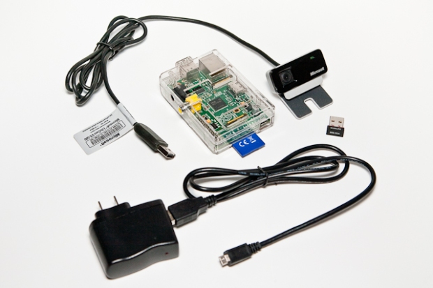
Motion
There are many posts on the Internet, demonstrating how to build a Raspberry Pi-powered motion-activated camera system. One of the more frequently used off-the-shelf applications for these projects is Motion. According to their website, ‘Motion is a program that monitors the video signal from one or more cameras and is able to detect if a significant part of the picture has changed; in other words, it can detect motion‘. Motion uses a technique known as visual motion detection (VMD) to compare a series of sequential camera frames for differences at a pixel level. A change between a series of sequential frames is an indication of movement.
Motion has the ability to stream images from a webcam and server them from it’s built-in web server, with little or no configuration. In addition, Motion is easily configured to work with streaming video applications like the very popular FFmpeg, and save images to databases like mySQL or PostgreSQL. Motion can also execute external scripts such as python or shell. In this post, we are going to use Motion’s most basic features, motion detection and web-streaming.
Installing Motion
Firmware Update
Before installing Motion, I recommend ensuring your Raspberry Pi is up-to-date with the latest software and firmware. Updating firmware is not necessary. However, I was recently helping someone with camera issue on their Raspberry Pi. Finding a few suggestions online for similar problems, we updated the firmware on the Raspberry Pi. It fixed the problem. Installing firmware can sound a bit intimidating. However, Liam McLoughlin (hexxeh) has made the process easy with rpi-update. I have used it successfully on multiple Raspberry Pi’s. Three commands is all it takes to update your Raspberry Pi to the latest firmware.
Software Update
You should also update your Raspberry Pi’s existing software. To update your Raspberry Pi’s software, execute the following apt-get commands:
sudo apt-get update && sudo apt-get upgrade
If you don’t do this on a regular basis, as recommended, these could take up to several minutes. Watch for errors. If there are any errors, try to run the command again. Sometimes the Raspberry Pi cannot connect to all code repositories for updates.
Installing Motion
Once the updates are complete, install Motion by issuing the following command:
sudo apt-get install motion
Enabling Motion
As the installation completes, you should see a warning in the command shell about Motion being disabled by default.
...
Adding user `motion' to group `video' ...
Adding user motion to group video
Done.
[warn] Not starting motion daemon, disabled via /etc/default/motion ... (warning).
Setting up ffmpeg (6:0.8.4-1) ...
pi@garyrasppi ~ $
To enable Motion (the motion daemon), we need to edit the /etc/default/motion file.
sudo nano /etc/default/motion
Change the ‘start_motion_daemon‘ parameter to ‘yes’.

Configuring Motion
Motion is easy to customize with loads of parameters you can tweak based on your needs. Motion has no GUI. All configuration is all done through Motion’s configuration file (/etc/motion/motion.conf). Before editing the configuration file, we need to change the permissions on it, so Motion can get access to it. While we are at it, we will also change permissions on the folder where Motion stores captured images.
sudo chmod -R 777 /etc/motion/motion.conf
sudo chmod -R 777 /tmp/motion
After changing the permissions, to configure Motion, open the Motion’s configuration file in a text editor, as root (sudo). I like using Nano. The configuration file can be opened in Nano with the following command:
sudo nano /etc/motion/motion.conf
Motion’s configuration file is lengthy. However, it is broken down into logical sections, making finding the setting you are looking for, easy. First, we need to change the ‘Live Webcam Server’ section of configuration. Below are the default settings:
############################################################
# Live Webcam Server
############################################################

# The mini-http server listens to this port for requests (default: 0 = disabled)
webcam_port 8081

# Quality of the jpeg (in percent) images produced (default: 50)
webcam_quality 50

# Output frames at 1 fps when no motion is detected and increase to the
# rate given by webcam_maxrate when motion is detected (default: off)
webcam_motion off

# Maximum framerate for webcam streams (default: 1)
webcam_maxrate 1

# Restrict webcam connections to localhost only (default: on)
webcam_localhost on

# Limits the number of images per connection (default: 0 = unlimited)
# Number can be defined by multiplying actual webcam rate by desired number of seconds
# Actual webcam rate is the smallest of the numbers framerate and webcam_maxrate
webcam_limit 0
The first thing you will want to change is Motion’s default setting that restricts image streaming to ‘localhost‘, only ( ‘webcam_localhost on‘). This means you can only view images in a web browser on the Raspberry Pi, not remotely over your network. Change that line of code to read ‘webcam_localhost off‘.
The next setting I recommend changing for security purposes is the default port Motion’s web server uses to stream images, 8081. Security through obscurity is better than no security at all. Change port 8081 to a different arbitrary port, for example, 6789 (‘webcam_port 6789‘). Just make sure you don’t pick a port already in use by another service or application. Having made this change, if your Raspberry Pi’s local IP address is 192.168.1.9, images from the webcam should be accessible at 192.168.1.9:6789.
The other two settings in this section you can play with are the webcam quality and maximum frame-rate. You will have to adjust this based on your network speed and the processing power of your Raspberry Pi. The default settings are a good place to start. I changed my quality from the default of 50 to 80 (‘webcam_quality 80‘), and changed my max frame-rate to 2 (‘webcam_maxrate 2‘).
Speaking of quality, the other two settings you may want to change are the width and height of the image being captured by Motion. The ‘Capture device options’ section is where we change these settings. As the configuration’s comments suggest, these settings are dependent on your camera. Check the camera’s available image sizes; you will need to use one of those size combinations. I have mine set to an average size of 352 x 288. This is a good size for those of us with a slower network, or when streaming video over the Internet to mobile web browser. Conversely, a larger image is better for viewing over your local network.
Image size, like compression quality, and frame-rate are dependent on processing power of your Raspberry Pi and it’s OS (Raspbian, Debian, Arch, etc.). You may need to play with these settings to get the desired results. I couldn’t stream images larger than 352 x 288 over the Internet, with my Raspberry Pi, even though my webcam could capture up to 640 x 480 pixels.
# Image width (pixels). Valid range: Camera dependent, default: 352
width 352

# Image height (pixels). Valid range: Camera dependent, default: 288
height 288
It’s important to remember, each time you make changes to Motion’s configuration file, you must restart Motion, using the following command.
sudo /etc/init.d/motion restart
Viewing Your Webcam Remotely
To view your webcam’s output from another device on your local network, point your web browser to the IP address of your Raspberry Pi, and add the port you assigned in Motion’s configuration file. Motion may take up to 15-20 seconds to start responding in the browser. If it takes longer, you probably have your image size, frame-rate, and compression settings to high for your Raspberry Pi.
Over the Internet
Enabling your webcam’s output over the Internet is relatively easy with the average home router and Internet service provider. Suppose the IP address of my Raspberry Pi, on my local network, is 192.168.1.9. Suppose I assigned port 6789 to Motion’s web server. Lastly, suppose my router’s external Internet IP address is 113.45.67.88. With this information, I can create a port-forwarding rule in my router, allowing all external HTTP traffic over TCP to 113.45.67.88:3456, to be automatically forwarded internally to 192.168.1.9:6789. The external port, 3456, is totally arbitrary, just make sure you don’t pick a port already in use.

IMPORTANT SECURITY NOTE: There are no passwords or other network protection used with this method. Make sure to keep the external IP address and port combination private, and always stop Motion, or better yet your Raspberry Pi, when not in use. Otherwise, someone could potentially be watching you!
Down at the local coffee shop, I decide to check if the mailman has delivered my new Raspberry Pi to the front porch. Having set-up port-forwarding, I enter 113.45.67.88:3456 in my smartphone’s web browser. My Internet provider routes the HTTP request to my Internet router. My router receives the request and forwards it over my local network to 192.168.1.9:6789, where Motion’s built-in web server on my Raspberry Pi is running. Motion’s web server responds by streaming still images back to my phone at the coffee shop when it detects motion. Still no sign of the mailman or my Raspberry Pi…
Static IP Addresses
I recommend using a static IP address for your Raspberry Pi, versus DHCP, if possible. Else, you will have to change your router’s port-forwarding rules each time your Raspberry Pi’s DHCP lease is renewed and its local IP address changes. There are some ways to prevent addressed from changing frequently with DHCP, if your router supports it. Look for configurable lease times or reservations options in your router’s configuration; these may be able to be extended.
Locating Your External Internet IP Address
What is your router’s external Internet IP address? To find mine, I looked in Netgear’s Router Status window. You can also use a ‘tracert’ from the command line, if you know what to look for in the output.
Since I do not pay my Internet-provider for a static external Internet IP address, the address my provider assigns to my router is dynamic. It can and will change, sometimes almost never, or sometimes daily. The frequency of change depends on your provider. To view your webcam’s images, you will need to know your router’s current external Internet IP address.
Motion Example
Here are some example from a Microsoft LifeCam VX-500 and Logitech Webcam C210 webcams. The highest quality I could consistently stream over the Internet, from my Raspberry Pi 512Mb Model B, with both Soft-float Debian “wheezy” and Raspbian “wheezy”, was 352 x 288 at 80% compression and 2 fsp max. Locally on my LAN, I could reach a frame size of 640 x 480 pixels.
In the first example, I’ve placed the Raspberry Pi in a plastic container to protect it, and mounted the webcam in a flower box. Viewing the feed over my local network, we are able to watch the hummingbirds without scaring them.

In the next two images, I’ve turned on Motion’s ‘locate box’ option, which tracks the exact area within the image that is moving. As the person come into view of the camera mounted near the front door, Motion detects and outlines the area of the images where it detects movement.


In the next video, you see the view from a Google Nexus 7 tablet. My wife and I use the Raspberry Pi surveillance system to watch our backyard when our kids are outside (the camera is no substitute for adult supervision when the kids are in the pool).
This last image is from my iPhone, while shopping at the local grocery store. My wife was impressed with my port-forwarding knowledge. OK, not really, but she did enjoy showing off the Christmas tree to friends, remotely, even if it wasn’t in motion.

Useful Links
Here are a few links to other useful articles on the use of Motion with the Raspberry Pi:
Raspberry Pi-Powered Dashboard Video Camera Using Motion and FFmpeg
Setup a webcam security system with Ubuntu Linux and Motion
Guest blog #7: Bird table webcam by Francis Agius
motion(1) – Linux man page (good source for understand Motion config)
Linux UVC Supported Devices (a good starting point for buying a webcam)
Installing a Miniature WiFi Module on the Raspberry Pi (w/ Roaming Enabled)
Posted by Gary A. Stafford in Raspberry Pi on December 30, 2012
Background
In a earlier post, Installing a Miniature WiFi Module on the Raspberry Pi (w/o Roaming Enabled), I detailed the installation and configuration of a Miniature WiFi Module, from Adafruit Industries, on a RaspPi running Soft-float Debian “wheezy”. As I mentioned in that post, there was more than one method of configuring the WiFi Module (WNIC) on a WLAN, based on the research I did. I chose the simple method of hard-coding a single WLAN configuration into the ‘/etc/interfaces’ file.
Recently, while installing the same type WiFi Module (WNIC) on a RaspPi running Raspbian “wheezy”, I chose the alternate method. This involves adding the WLAN configuration to the wpa_supplicant configuration file (‘/etc/wpa_supplicant/wpa_supplicant.conf’). You can add multiple WLAN configurations to the wpa_supplicant configuration file. This allowing the RaspPi to roam from networks to network, automatically connecting to those that are configured.
If you’re not comfortable configuring networks from the command shell, you can also use the wpa_gui application (aka wpa_suppicant user interface) from the RaspPi’s desktop. It allows you to edit the same configuration from a gui, just as we will do manually in the command shell.

Installing the WiFi Module Driver
Copy the ‘Linux and Android’ Realtek driver folder from the CD, supplied by the manufacturer, to the ‘tmp’ folder on the RaspPi using WinSCP. Then, run the following commands:
cd /
cd /tmp/Linux\ and\ Android
chmod +x install.sh
sudo ./install.sh
Remember to select #1 when asked to choose a card type:
...
Please select card type(1/2):
1) RTL8192cu
2) RTL8192du
#? 1
You can insert the WiFi Module at this point in the process.
Installing Wireless LAN Security Protocol Software
As detailed in the earlier post, we need to install software that allows us to configure and connect to our WPA/WPA2-secured wireless network. The particular software is referred to as ‘wpa_supplicant’. To install ‘wpa_supplicant’ and the ‘wpagui’, enter the following commands. Note this will check for any upgrades to the RaspPi’s existing software, first. This is a commonly-recommended step. The upgrade command might take a few minutes if you haven’t run this on your RaspPi in a while.
sudo apt-get update && sudo apt-get upgrade
sudo apt-get install wpasupplicant wpagui
Configuring the New WiFi Adapter
Examine the contents of the ‘/etc/networks/interfaces’ file, by entering the following command:
sudo cat /etc/network/interfaces
Unlike in the first post, we will make no changes to this file. The ‘/etc/networks/interfaces’ file should have the default settings for both the current NIC (eth0) as well as for the WNIC (wlan0), as shown below. Note the reference to the ‘/etc/wpa_supplicant/wpa_supplicant.conf’ file. Why are the file’s contents different than in the first post? Because we installed ‘wpagui’.
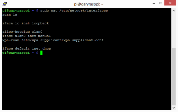
WPA Supplicant Configuration
Enter the following command, substituting your own SSID (‘your_ssid’) and passphrase (‘your_passphrase’).
wpa_passphrase your_ssid your_passphrase
Based your SSID and passphrase, this command will generate a pre-shared key (PSK), similar to the following. Save or copy the PSK to the clipboard; we will need it in the next step.

Next, open the ‘/etc/wpa_supplicant/wpa_supplicant.conf’ file using Nano, by entering the following command:
sudo nano /etc/wpa_supplicant/wpa_supplicant.conf
Add the following code at the end of the file. Remember to substitute your_ssid and your_psk_or_passphrase. Note the following settings are specific to my WPA2-secured network. If you are using WPA, refer to this post for the correct WPA settings.
network={
ssid=&quot;your_ssid&quot;
proto=RSN
key_mgmt=WPA-PSK
pairwise=CCMP
group=CCMP
psk=&quot;your_psk_or_passphrase&quot;
}
Your final file should look similar to this:

Save the file and exit Nano. Lastly, execute the following series of commands to assign an IP address to the new WNIC.
sudo wpa_supplicant -d -c /etc/wpa_supplicant/wpa_supplicant.conf -i wlan0 -D wext
sudo ifconfig wlan0 up
sudo dhclient wlan0
sudo wpa_supplicant -B -c /etc/wpa_supplicant/wpa_supplicant.conf -i wlan0 -D wext
ip addr show wlan0
You should see an IP Address for ‘wlan0’ displayed. That it, shutdown the RaspPi, remove the Ethernet cable, and restart the RaspPi. Use a program like ‘Advanced IP Scanner’ for Windows, or ‘Fing’ for iOS, to discover the wireless IP address of the RaspPi. The RaspPi will show up with the WiFi chipset manufacturer’s name, ‘REALTEK SEMICONDUCTOR’ or ‘REALTEK SEMICONDUCTOR CORP.’. Use this address to re-connect to the RaspPi.
Need to add another network’s configuration? Simply enter the information in the ‘/etc/wpa_supplicant/wpa_supplicant.conf’ and restart. Here are a few good articles I found on configuring a WiFi Module on the RaspPi with roaming:
http://hostap.epitest.fi/wpa_supplicant/
http://www.cyberciti.biz/faq/linux-ndiswrapper-wpa_supplicant-howto/
http://linux.die.net/man/5/wpa_supplicant.conf
http://ubuntuforums.org/showthread.php?t=1259003
http://ubuntuforums.org/showthread.php?t=318539
http://unix.stackexchange.com/questions/7817/how-to-find-out-which-wi-fi-driver-is-installed
Installing TightVNC on the Raspberry Pi
Posted by Gary A. Stafford in Raspberry Pi on December 26, 2012
Sometimes connecting a keyboard, mouse, and monitor to Raspberry Pi is really inconvenient. But what’s the alternative if you want to interact directly with your Raspberry Pi’s GUI? PuTTY is an excellent SSH client, but the command shell is no substitute. WinSCP is an excellent SFTP client, but again, no substitute for a fully-functional GUI. The answer to this predicament? TightVNC, by GlavSoft LLC.
Background
According to TightVNC Software’s website, ‘TightVNC is a free remote control software package. With TightVNC, you can see the desktop of a remote machine and control it with your local mouse and keyboard, just like you would do it sitting in the front of that computer.‘
What is VNC? According to Wikipedia, ‘Virtual Network Computing (VNC) is a graphical desktop sharing system that uses the RFB protocol (remote framebuffer) to remotely control another computer. It transmits the keyboard and mouse events from one computer to another, relaying the graphical screen updates back in the other direction, over a network.‘
If you are a Windows user, you are no doubt familiar with Microsoft’s Remote Desktop Connection (RDC). GlavSoft’s TightVNC and Microsoft’s RDC are almost identical in terms of functionality.
Installation
TightVNC has two parts, the client and the server. The TightVNC Server software is installed on the Raspberry Pi (RaspPi). The RaspPi acts as the TightVNC Server. The client software, the TightVNC Java Viewer, is installed on a client laptop or desktop computer.
I used PuTTY from my Windows 8 laptop to perform the following installation and configuration. I successfully performed this process on a RaspPi Model B, with copies of both Raspbian “wheezy” and Soft-float Debian “wheezy”.
TightVNC Server
To install the TightVNC Server software, run the following commands from the RaspPi. The first command is are optional, but usually recommended before installing new software.
sudo apt-get update && sudo apt-get upgrade
sudo apt-get install tightvncserver
To test the success of the TightVNC Server installation, enter ‘vncserver‘ in the command shell. The first time you run this command, you will be asked to set a VNC password for the current user (‘pi’). The password can be different than the system password used by this user. After inputting a password, you should see output similar to the below screen grab. This indicates that TightVNC is running.

By default, TightVNC runs on a port 5901. To verify TightVNC is running on 5901, enter the command ‘sudo netstat -tulpn‘. You should see output similar to the screen grab below. Note the entry for TightVNC on port 5901. Stop TightVNC by entering the ‘vncserver -kill :1‘ command.
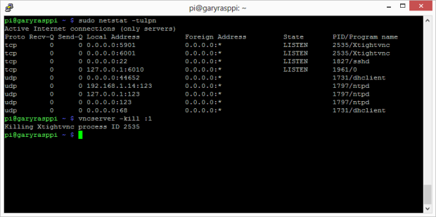
You may have noticed TightVNC was also running on port 6001. This is actually used by the X Window System, aka ‘X11’. A discussion of X11 is out of scope for this post, but more info can be found here.
Automatic Startup
For TightVNC Server to start automatically when we boot up our RaspPi, we need to create an init script and add it to the default runlevels. I had a lot of problems with this part until I found this post, with detailed instructions on how to perform these steps.
Start by entering the following command to create the init script:
sudo nano /etc/init.d/tightvncserver
Copy and paste the init script from the above post, into this file. Change the user from ‘pi’ to your user if it is different than ‘pi’. Save and close the file.
Next, execute these two commands to add the script to the default runlevels:
sudo chmod 755 /etc/init.d/tightvncserver
sudo update-rc.d tightvncserver defaults
To complete the TightVNC Server installation, restart the RaspPi.
TightVNC Java Viewer
According to the website, TightVNC Java Viewer is a fully functional remote control client written entirely in Java. It can work on any computer where Java is installed. It requires Java SE version 1.6 or any later version. That can be Windows or Mac OS, Linux or Solaris — it does not make any difference. And it can work in your browser as well. On the client computer, download and unzip the TightVNC Java Viewer. At the time of this post, the current TightVNC Java Viewer version was 2.6.2.
Once the installation is complete, double-click on the ‘tightvnc-jviewer.jar’ file. Running the Java jar file will bring up the ‘New TightVNC Connection’ window, as seen in the example below. Input the RaspPi’s IP address or hostname, and the default TightVNC port of 5901. The use of SSH tunneling is optional with the TightVNC Viewer. If you are concerned about security, use SSH.

Clicking the ‘Connect’ button, you are presented with a window to input the user’s VNC password.

Optionally, if using SSH, the user’s SSH password is required. Again, the same user can have different SSH and VNC passwords, as mine does.

If everything was installed and configured correctly, you should be presented with a TightVNC window displaying the RaspPi’s desktop. Note the TightVNC toolbar along the top edge of the window. The ‘Ctrl’ and ‘Alt’ buttons are especially useful to send either of these two key inputs to the RaspPi on a Windows client. Using the ‘Set Options’ button, you can change the quality of TightVNC’s remote display. Note these changes this can affect performance.

Congratulations, no more connecting a keyboard, mouse, and monitor to you RaspPi to access the GUI. I suggest reading the documentation on the TightVNC website, as well as the ‘README.txt’ file, included with the TightVNC Java Viewer. There is a lot more to TightVNC than I have covered in this brief introductory post, especially in the README.txt file. -gs
Installing a Miniature WiFi Module on the Raspberry Pi (w/o Roaming Enabled)
Posted by Gary A. Stafford in Raspberry Pi on December 25, 2012
One of the best purchases I’ve made recently was a Miniature WiFi Module for my Raspberry Pi, from Adafruit Industries. No more having my RaspPi tethered to an Ethernet port on my wireless router. I can have my RaspPi with me, wherever I’m working. At the same time, I have Internet access on both my laptop and the RaspPi. All this for less than $12!

Background
The Miniature WiFi Module is technically a wireless network interface controller (WNIC). It connects the RaspPi to a wireless local area network (WLAN). Wherever you see the word ‘Interface’ in this post, it is referring to either the new Miniature WiFi Module, or the built-in network interface controller (NIC), which connects the RaspPi to a local area network (LAN) via Ethernet.
In researching how to properly install and configure the WiFi Module, I read a number of articles and posts on the Internet. The simplest approach I found was presented in this article by Macro M.C. on MacroMC.com. Much of the following is based on his article. Marco directly edits the ‘interfaces’ file, instead of also editing the ‘wpa_supplicant.conf’ file, as is demonstrated in other posts. I will only be connecting my RaspPi to a single WLAN in this post. If you will be switching between multiple WLANs with your RaspPi, you might want to investigate the alternate method of editing the ‘wpa_supplicant.conf’ file, or using the wpa supplicant user interface, instead.
I will be installing and configuring my RaspPi using a Windows laptop. However, if you are using a Mac or Linux-based computer, you shouldn’t need change these directions. Also, I am using the WPA2-Personal security protocol on my home’s wireless network. These directions should work for both commonly used WPA and WPA2 wireless network security protocols; I will explain further in step 2. Lastly, since I largely develop Java SE Embedded applications for the Raspberry Pi, I have installed Soft-float Debian “wheezy” on my RaspPi. However, these directions should also work for the more commonly installed Raspbian “wheezy”, as well.
Getting Started
The configuration and installation of the Miniature WiFi Module takes less 15 minutes. I’ve broken the process down into three steps:
- Installing the WiFi Module driver
- Installing wireless LAN security protocol software
- Configuring the new WiFi Module
Before we start, make sure you have the following items available:
- Your wireless network’s name (aka SSID)
- Your network security key (aka passphrase)
- SSH enabled on your RaspPi
- LAN access to your RaspPi
- Internet access from your RaspPi
- PuTTY to your RaspPi
- WinSCP to copy files to your RaspPi
- Advanced IP Scanner, Fing, or similar network scanning software (optional)
Installing the WiFi Module Driver
Don’t insert the WiFi Module into the RaspPi, yet. Instead, connect the RaspPi to your LAN using an Ethernet cable. Make sure the RaspPi has Internet access. Insert the small CD that comes with the WiFi Module into your laptop’s CD/DVD player. Connect to the RaspPi from your laptop using WinSCP. Copy the ‘Linux and Android’ folder from the CD to the ‘tmp’ folder on the RaspPi, as shown below.

Before we install the driver, let’s examine the current network interface configuration on the RaspPi. Log into your RaspPi using PuTTY. Using the ifconfig command, you should only see the built-in NIC (eth0), as shown in the example below.
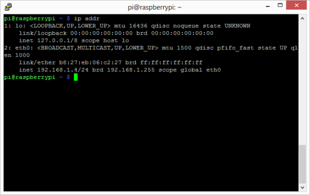
Realtek is the WiFi Module’s chipset manufacturer. To install the Realtek WiFi Module driver on the RaspPi, enter the following series of commands.
cd /
cd /tmp/Linux\ and\ Android
chmod +x install.sh
sudo ./install.sh
During the install you’ll be prompted to select between two card types, enter 1;
...
Please select card type(1/2):
1) RTL8192cu
2) RTL8192du
#? 1
Installing Wireless LAN Security Protocol Software
After installing the driver, we need to install software that allows us to configure and connect to our WPA-secured wireless network. The particular software is referred to as ‘wpa_supplicant’. According to Jouni Malinen, wpa_supplicant is a WPA Supplicant for Linux, BSD, Mac OS X, and Windows with support for WPA and WPA2 (IEEE 802.11i / RSN). It is suitable for both desktop/laptop computers and embedded systems. Supplicant is the IEEE 802.1X/WPA component that is used in the client stations. It implements key negotiation with a WPA Authenticator and it controls the roaming and IEEE 802.11 authentication/association of the wlan driver.
To install wpa_supplicant, enter the following commands. Note this will check for any upgrades to the RaspPi’s existing software, first. This is a commonly-recommended step. The upgrade command might take a few minutes if you haven’t run this on your RaspPi in a while.
sudo apt-get update && sudo apt-get upgrade
sudo apt-get install wpasupplicant
Next, enter the following command, substituting your own SSID (‘your_ssid’) and passphrase (‘your_passphrase’).
wpa_passphrase your_ssid your_passphrase
Based your SSID and passphrase, this command will generate a pre-shared key (PSK), similar to the following. Save or copy the PSK to the clipboard; we will need it in the next step.
Configuring the New WiFi Adapter
The last step is to configure the new WiFi Module (WNIC) for your WLAN. Open the ‘/etc/networks/interfaces’ file using Nano, by entering the following command.
sudo nano /etc/network/interfaces
This file will only have the default settings for the current NIC (eth0), as shown below.

To add the new WNIC (wlan0), enter the following lines of code to the end of the ‘interfaces’ file. Substitute you SSID (‘your_ssid’) in quotes and the PSK you generated in the previous step. Do not use the SSID and PSK below, it will not work for your network, it is only an example.
auto wlan0
allow-hotplug wlan0
iface wlan0 inet dhcp
   wpa-ssid "your_ssid"
   wpa-psk b2abb0fcd2f4527e11817de0823a57bb19ba4622f4595062c94ec4dd1370b5fe
Save the file and exit Nano. Shutdown the RaspPi and remove the Ethernet cable. Insert the Miniature WiFi Module and restart the RaspPi. You should not run the RaspPi with both the LAN and WLAN Interfaces connected.
Finding the Raspberry Pi’s Wireless Address
Since you used Dynamic Host Configuration Protocol (DHCP) in the interface’s configuration, the Module has been assigned a new IP address. To find the RaspPi’s new wireless IP address, log directly into the RaspPi and use the ifconfig command. Alternately, we can use a program like ‘Advanced IP Scanner’ for Windows or ‘Fing’ for iOS, to discover the address of the RaspPi. The RaspPi will show up with the WiFi chipset manufacturer’s name, ‘REALTEK SEMICONDUCTOR’ or ‘REALTEK SEMICONDUCTOR CORP.’.
In the example below from Fing on an iPhone, there are two wireless RaspPi’s on my network, an inactive wireless RaspPi at 192.168.1.7, and my active wireless RaspPi at 192.168.1.9.

Here is another view of my network using Advanced IP Scanner on Windows. My active wireless RaspPi at 192.168.1.9.

If you are unable to find your RaspPi on the WLAN, re-connect to the RaspPi directly and check for errors. I had to do this on more than a few occasions while researching this post, mostly due to typos in my interface file. Try rebooting the RaspPi and watch the shutdown and boot-up screens for errors.; network errors will often show up here.
Use the RaspPi’s new wireless IP address you found to connect back into your RaspPi with PuTTY. To better understand how the new WiFi Module (WNIC) is configured, run the ifconfig command, again. This time you should see both the NIC (eth0) and WNIC (wlan0).

Congratulations, your RaspPi is wireless. Please feel free to ‘move about the cabin’. -gs
Gary Stafford
AWS Area Principal Solutions Architect | 10x AWS Certified Pro | DevOps | Data/ML | Serverless | Polyglot Developer | Former ThoughtWorks and Accenture
